

'SHAPING INDUSTRIES WITH THE FINEST STEEL'
'SHAPING INDUSTRIES WITH THE FINEST STEEL'
Tesco Steel & Engineering manufactures ASME B16.47 Series B Class 300 weld neck flanges — large diameter welding necks in the compact Series B (formerly API 605) pattern, typically 30–50% lighter than Series A where the two differ: the economical choice for process plants, tank farms and offshore topsides. Sizes NPS 26–60 (DN 650–1500), raised face standard with RTJ or flat face on request, forged or rolled-ring forged, bored to your pipe wall. This page is the complete reference: the full 18-size dimension chart in mm with bolt circles, stud counts, hole sizes and weights, the pressure–temperature table in bar, the Series B vs Series A comparison and the material grades we produce — from A105 and A694 pipeline grades to SS 316 and duplex. ISO 9001:2015 certified, made in Mumbai, India — exported worldwide.
ASME B16.5 stops at NPS 24; from 26″ up, large diameter steel flanges belong to ASME B16.47 — and Series B is the engineer’s economy of the two patterns. Inherited from API 605, the refinery and tank-farm flange standard, it reaches the same Class 300 rating as Series A with a smaller ring and more, smaller bolts on a tighter circle. At the sizes where the patterns differ, 26″–36″, the saving runs 30–50% — 181 kg against 274 kg at 26″ — which is why refinery and petrochemical headers, gas-plant and LNG piping, offshore topsides and FPSO process lines, compressor connections and vessel nozzles specify it wherever the mating equipment allows.
One relationship to know: from NPS 38 upward, B16.47 defines Series A Class 300 with the Series B dimensions — the two series converge, and this chart is the pattern they share. The weld neck hub gives butt-welded strength and a radiographable joint on large pipe. Two B16.47 habits apply as always: the bore is not standardised (each flange is bored to the pipe OD × wall on the order), and at 26″–36″ nothing in Series B interchanges with Series A or B16.5 drilling. Ratings follow ASME B16.5 Table 2, reproduced below in bar.
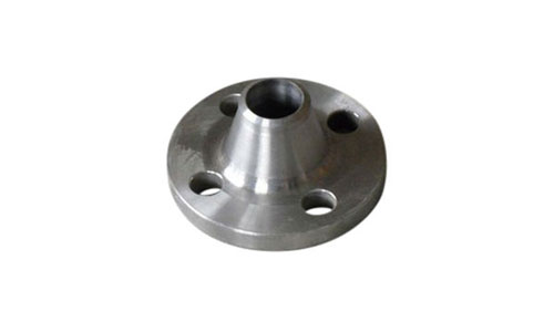
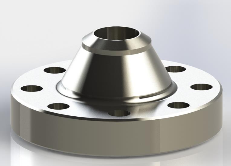
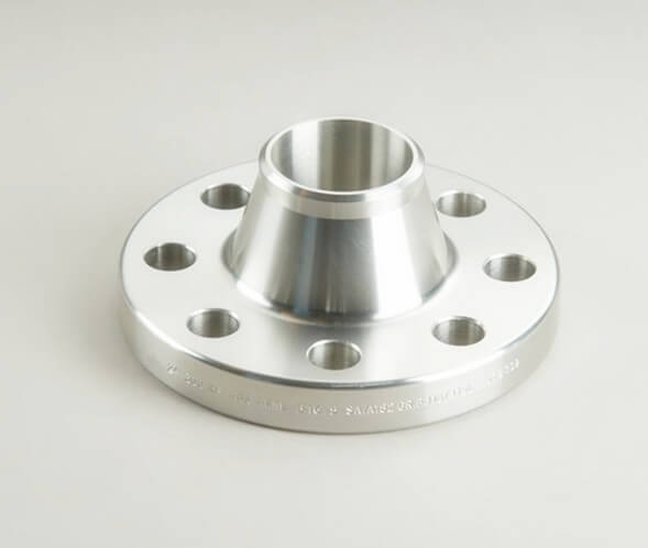
“Class 300” (also written 300 lb or #300, roughly PN 50) is a pressure–temperature rating class, and B16.47 adopts the ASME B16.5 Table 2 ratings for it — identical for both series, so Series B gives up nothing in rating for its lighter build:
| Temperature °C | Group 1.1 — A105 / A350 LF2 / A694 | Group 2.1 — A182 F304 | Group 2.2 — A182 F316 |
|---|---|---|---|
| −29 to 38 | 51.1 | 49.6 | 49.6 |
| 100 | 46.6 | 42.2 | 43.2 |
| 150 | 45.1 | 38.5 | 39.5 |
| 200 | 43.8 | 35.7 | 36.8 |
| 250 | 41.9 | 33.4 | 34.4 |
| 300 | 39.8 | 31.6 | 32.6 |
| 350 | 37.6 | 30.3 | 31.3 |
| 400 | 34.7 | 29.4 | 30.4 |
| 450 | 28.8 | 28.8 | 29.4 |
Working pressure in bar (gauge) per ASME B16.5 Tables 2-1.1, 2-2.1 and 2-2.2, as adopted by B16.47. A694 high-yield grades rated per Group 1.1 unless otherwise agreed. Confirm for your exact material group, bolting and gasket.
All dimensions in mm per ASME B16.47-2020 Series B. Letters follow the figure: O = outer diameter, C = flange thickness (including the 2 mm raised face), X = hub diameter at base, A = hub diameter at the weld bevel, R = raised face diameter, V = length through hub (measured from the raised face), B = bolt circle (PCD), H = bolt hole diameter. Prefer it on paper? Download the full Series B Class 300 dimensions datasheet (PDF) — the same chart with the drawing, ratings, materials and ordering notes, ready for the workshop.
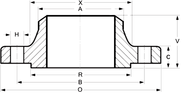
Weld Neck Flange Dimension Reference — ASME B16.47 Series B
| Size in Inch | Size in mm | Outer Diameter | Flange Thickness | Hub OD | Weld Neck OD | RF Diameter | Length Through Hub | PCD | No. of Studs | Hole Ø | Stud Size | Approx Weight (kg) |
|---|---|---|---|---|---|---|---|---|---|---|---|---|
| O | C | X | A | R | V | B | — | H | — | |||
| 26 | 650 | 865 | 89.0 | 702 | 665.2 | 737 | 169.6 | 803.3 | 32 | 34.9 | 1 1/4 | 181 |
| 28 | 700 | 920 | 89.0 | 756 | 716.0 | 787 | 149.6 | 857.2 | 36 | 34.9 | 1 1/4 | 204 |
| 30 | 750 | 990 | 93.7 | 813 | 768.4 | 845 | 157.6 | 920.8 | 36 | 38.1 | 1 3/8 | 249 |
| 32 | 800 | 1055 | 103.2 | 864 | 819.2 | 902 | 168.6 | 977.9 | 32 | 41.3 | 1 1/2 | 311 |
| 34 | 850 | 1110 | 103.2 | 918 | 870.0 | 953 | 172.6 | 1031.9 | 36 | 41.3 | 1 1/2 | 340 |
| 36 | 900 | 1170 | 103.2 | 965 | 920.8 | 1010 | 180.6 | 1089.0 | 32 | 44.5 | 1 5/8 | 381 |
| 38 | 950 | 1220 | 111.2 | 1016 | 971.6 | 1060 | 191.6 | 1139.8 | 36 | 44.5 | 1 5/8 | 415 |
| 40 | 1000 | 1275 | 115.9 | 1067 | 1022.4 | 1114 | 198.6 | 1190.6 | 40 | 44.5 | 1 5/8 | 449 |
| 42 | 1050 | 1335 | 119.1 | 1118 | 1074.7 | 1168 | 204.6 | 1244.6 | 36 | 47.6 | 1 3/4 | 515 |
| 44 | 1100 | 1385 | 127.1 | 1173 | 1125.5 | 1219 | 214.6 | 1295.4 | 40 | 47.6 | 1 3/4 | 560 |
| 46 | 1150 | 1460 | 128.6 | 1229 | 1176.3 | 1270 | 222.6 | 1365.2 | 36 | 50.8 | 1 7/8 | 667 |
| 48 | 1200 | 1510 | 128.6 | 1278 | 1227.1 | 1327 | 223.6 | 1416.0 | 40 | 50.8 | 1 7/8 | 714 |
| 50 | 1250 | 1560 | 138.2 | 1330 | 1277.9 | 1378 | 234.6 | 1466.8 | 44 | 50.8 | 1 7/8 | 776 |
| 52 | 1300 | 1615 | 142.9 | 1383 | 1328.7 | 1429 | 242.6 | 1517.6 | 48 | 50.8 | 1 7/8 | 835 |
| 54 | 1350 | 1675 | 136.6 | 1435 | 1379.5 | 1480 | 239.6 | 1578.0 | 48 | 50.8 | 1 7/8 | 898 |
| 56 | 1400 | 1765 | 154.0 | 1494 | 1430.3 | 1537 | 268.6 | 1651.0 | 36 | 60.3 | 2 1/4 | 1177 |
| 58 | 1450 | 1825 | 154.0 | 1548 | 1481.1 | 1594 | 274.6 | 1712.9 | 40 | 60.3 | 2 1/4 | 1256 |
| 60 | 1500 | 1880 | 150.9 | 1599 | 1557.3 | 1651 | 271.6 | 1763.7 | 40 | 60.3 | 2 1/4 | 1302 |
| Series B (this page) | Series A | |
|---|---|---|
| Origin | API 605 (large-diameter CS flanges) | MSS SP-44 (pipeline flanges) |
| Geometry | Compact — more, smaller bolts, tight circle | Larger OD, thicker, fewer / larger bolts |
| Weight (26″ Cl.300) | ≈181 kg | ≈274 kg |
| At Class 300 | Differ at NPS 26–36; identical at NPS 38–60 — Series A adopts the Series B dimensions there | |
| Typical use | Process plants, tank farms, offshore topsides | Pipelines, valves, pumps, vessel nozzles |
Rule of thumb: match the mating equipment, and state the series on every drawing and enquiry. Our Series A Class 300 chart carries the companion table for NPS 26–36, where the two patterns genuinely differ.
B16.47 Series B Class 300 weld neck flanges are produced in the material families below — forged or rolled-ring forged, each with EN 10204 3.1 mill certificates, heat-number traceability and PMI on request:
| Material Family | Typical Flange Grades | Best suited to |
|---|---|---|
| Carbon Steel | ASTM A105 / A105N; A266 Cl.2 for large forgings | Process headers, tank farms, plant utility |
| High-Yield Pipeline | ASTM A694 F42, F46, F52, F56, F60, F65 | Matched to API 5L X42–X65 line pipe |
| LTCS | ASTM A350 LF2 Cl.1 / Cl.2, LF3 | Low-temperature service, impact tested |
| Stainless Steel | A182 F304/L, F316/L, F321 | Corrosive process & offshore service |
| Duplex / Super Duplex | A182 F51 (2205), F53 (2507) | High strength + chloride resistance, FPSO & topsides |
| Clad / Weld Overlay | CS + 316L, Inconel 625 or Cu-Ni face overlay | Corrosion resistance at carbon-steel cost — on request |
| EN Equivalents | P250GH, P355NH / L360NB (1.0582), 1.4404 — on request | European specifications |
Large diameter flanges are manufactured to order — use the Ask for Quote button or the inquiry form for today’s price and delivery position.
| Pressure Class | Series B (ex API 605) | Series A (ex MSS SP-44) |
|---|---|---|
| Class 75 | Series B Class 75 Weld Neck | — (no Series A Class 75) |
| Class 150 | Series B Class 150 Weld Neck | Series A Class 150 Weld Neck |
| Class 300 | Series B Class 300 Weld Neck (this page) | Series A Class 300 Weld Neck |
| Class 400 | Series B Class 400 Weld Neck | Series A Class 400 Weld Neck |
| Class 600 | Series B Class 600 Weld Neck | Series A Class 600 Weld Neck |
| Class 900 | Series B Class 900 Weld Neck | Series A Class 900 Weld Neck |
Below NPS 26, see our ASME B16.5 Class 300 weld neck chart. Related references: Weld Neck Flanges overview · Series B Class 300 Blind · All Flange Dimension Charts · Flange Weight Chart.
Series B reaches the full B16.5 Class 300 rating with 30–50% less weight than Series A at 26″–36″ — 181 kg against 274 kg at 26″ — through more, smaller bolts on a tighter circle.
From NPS 38 to 60 the standard defines Series A Class 300 with these Series B dimensions — this chart is the pattern both series share at the top of the range.
The tapered hub and full-penetration butt weld give the joint the strength and fatigue life of the pipe itself, with a weld geometry open to full radiography.
Refinery and petrochemical process headers, gas-plant and LNG piping, offshore topsides and FPSO process lines, compressor suction and discharge, large block valves and pump connections, vessel and heat-exchanger nozzles.
What is an ASME B16.47 Series B Class 300 weld neck flange?
A large diameter welding neck flange — NPS 26 through 60 — in the compact bolting pattern of ASME B16.47. Series B, formerly API 605, uses a smaller outside diameter, a thinner flange and more, smaller bolts on a tight bolt circle, making it typically 30-50% lighter than the Series A counterpart at the sizes where the two patterns differ. The weld neck type carries a tapered hub butt-welded to the pipe, giving the best stress distribution and fatigue life of any flange type at these sizes.
What are the dimensions of a B16.47 Series B Class 300 weld neck flange?
They are tabulated in ASME B16.47-2020 and reproduced in full in the chart above: for each of the eighteen sizes from NPS 26 to 60, the outer diameter, flange thickness, hub diameters at base and bevel, raised face diameter, length through hub, bolt circle, stud count, hole diameter and stud size — all in millimetres — plus the approximate weight. A 36 in flange, for example, is 1170 mm OD and 103.2 mm thick on a 1089 mm bolt circle with thirty-two 1-5/8 in studs, at about 381 kg.
Is the pressure rating the same as Series A Class 300?
Yes — both series use the ASME B16.5 Table 2 Class 300 ratings: 51.1 bar at 38 °C for A105, derating with temperature. Series B achieves the same rating with a smaller OD and more, smaller bolts on a tighter bolt circle. Note that at NPS 38-60, B16.47 defines Series A Class 300 with the Series B dimensions, so the two series coincide in that range.
How much lighter is Series B than Series A?
Typically 30-50% at the sizes where the two patterns differ, NPS 26 to 36: a 26 in Series B Class 300 weld neck weighs about 181 kg against 274 kg for Series A, and a 36 in about 381 kg against 578 kg. From NPS 38 upward the standard gives the two series identical Class 300 dimensions, so the saving applies to the 26-36 in range.
Series A or Series B — which do I need?
Match the mating equipment. Series B (ex API 605) is common in refineries, tank farms and offshore topsides; valves, pumps and older MSS SP-44 pipeline systems are usually Series A. When in doubt, compare the bolt count and bolt circle of the mating flange against the chart — at NPS 26-36 the two series never share a Class 300 drilling.
Are Series A and Series B Class 300 flanges interchangeable?
At NPS 26 to 36, no — different OD, bolt circle, bolt count and bolt size, so they can never bolt together there, nor to any B16.5 or B16.1 drilling. At NPS 38 to 60 the standard defines the two series with identical Class 300 dimensions. The series must still be stated on every enquiry and drawing, because at other sizes and classes the difference is real.
What is API 605 and how does it relate to B16.47 Series B?
API 605 was the American Petroleum Institute's standard for large-diameter carbon steel flanges on refinery and tank-farm piping — compact, economical patterns for moderate pressures. When ASME consolidated large diameter flanges into B16.47 in 1990, API 605 became Series B, dimension for dimension. Drawings still call up API 605 regularly, and a flange made to our chart mates with it exactly.
Does the thickness in the chart include the raised face?
Yes — for Class 300 the tabulated thickness C includes the 2 mm raised face, and the length through hub V is measured from the raised face. One Series B subtlety: the hub diameter at the bevel A is listed in B16.47 slightly above the pipe OD — the weld end is machined to match the pipe on the order.
Why is the bore not shown in the dimension table?
Because ASME B16.47 deliberately leaves it to the purchaser. Large diameter pipe is ordered by wall thickness rather than schedule, so there is no standard bore to print — the flange is bored to match the pipe stated on the order. Give the pipe OD and wall thickness (or the exact ID) with your enquiry; our chart weights assume a bore for STD (9.53 mm) wall pipe.
How much does a B16.47 Series B Class 300 weld neck flange weigh?
From the weight column in our chart: a 26 inch weighs about 181 kg, a 36 inch about 381 kg, a 48 inch about 714 kg and a 60 inch about 1302 kg. These are approximate carbon-steel weights bored for STD wall pipe; the exact weight varies with the bore and material.
Why do the bolt counts and stud sizes alternate through the chart?
The Series B Class 300 pattern balances bolt load size by size rather than in long runs, so count and stud size alternate as the chart climbs — a 36 in flange carries thirty-two 1-5/8 in studs while a 38 in carries thirty-six of the same size, and a 32 in steps down to thirty-two studs where the 30 in had thirty-six. Always count holes and measure the bolt circle against the mating flange rather than assuming a trend.
Which gasket and bolts are used with these flanges?
Spiral wound gaskets to ASME B16.20 with inner ring — standard thinking at these diameters and this class — or non-metallic gaskets to B16.21 on milder duty, with stud bolts and heavy hex nuts: A193 B7 / A194 2H for carbon steel, B8M Class 2 for stainless flanges. Studs run 1-1/4 to 2-1/4 in on this chart, 32 to 48 per flange, and the holes are drilled 3.2 mm larger than the stud. RTJ facings are available on request for critical service.
What materials are available for B16.47 Series B flanges?
Carbon steel ASTM A105/A105N and A266 Cl.2 for large forgings, high-yield A694 F42 through F65 matched to API 5L X42-X65 pipeline pipe, low-temperature A350 LF2/LF3, stainless A182 F304/L, F316/L and F321, duplex F51 and super duplex F53, plus carbon-steel flanges with 316L, Inconel 625 or copper-nickel weld overlay on request. EN equivalents such as P250GH, P355NH and 1.4404 are available — all with EN 10204 3.1 certificates, 3.2 on request.
Why choose a weld neck at these sizes?
Because at 26 to 60 in and Class 300 pressures the piping loads are serious and the joint lives on its fatigue performance. The weld neck's tapered hub feeds bending and pressure loads gradually from flange ring into pipe wall, and its full-penetration butt weld can be radiographed — which matters on process headers, compressor connections and offshore topsides where joint integrity is documented.
What facing do these flanges come with?
A 2 mm raised face as standard, serrated to 125-250 microinch Ra (3.2-6.3 micrometre) for spiral wound and soft gaskets; RTJ or flat face on request — RTJ for critical hydrocarbon service. State the facing with the enquiry.
How are your B16.47 flanges manufactured, tested and certified?
Forged from certified ingots or blooms, or rolled-ring forged at the larger diameters, then normalised, quenched-and-tempered or solution annealed per the material specification. Dimensional inspection follows ASME B16.47 tolerances with face finish per MSS SP-6, and marking per B16.47 and MSS SP-25 including "B16.47 SER. B" and "CL 300". Every batch ships with EN 10204 3.1 certificates; UT per ASTM A388, MPI/DPT, PMI, Charpy impact testing, NACE MR0175, PED and IBR compliance and 3.2 endorsement are available on request.
What other names does this flange go by?
ANSI B16.47 Series B 300 lb WNRF flange, API 605 Class 300 weld neck flange, 300# compact large diameter welding neck flange and 26-60 in WN flange all describe the same product, and the rating sits at roughly PN 50 in metric terms. ANSI and ASME B16.47 are the same standard — custodianship moved to ASME but the old names, API 605 especially, persist on drawings.
What sizes does B16.47 cover, and what about smaller flanges?
B16.47 covers NPS 26 through 60 — eighteen sizes in Series B at Class 300, all in the chart above. Below 26 in, large flanges are B16.5 territory: our Class 300 weld neck dimensions page carries NPS 1/2 to 24 with the same style of chart, and the drilling families line up so systems transition cleanly at the 24/26 in boundary.