

Tesco Steel & Engineering manufactures SAE J518 blind flanges — the solid, no-bore blanking flange used to seal off unused hydraulic pump, motor, valve, and manifold ports. Available in Code 61 (3000 PSI) and Code 62 (6000 PSI) series. SS 316, Duplex, Carbon Steel, Inconel, Monel. Size 3/8" to 5" NB. 34–420 bar. ISO 9001:2015 certified. Made in India.
TES-LOK SAE Blind Flange
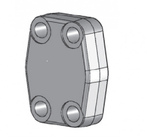
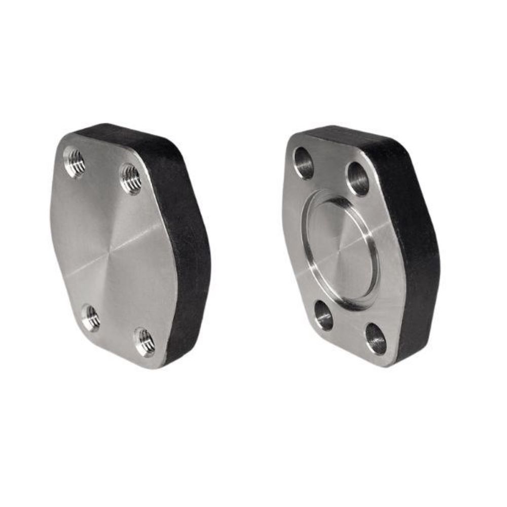
SAE Blind Mono Flange
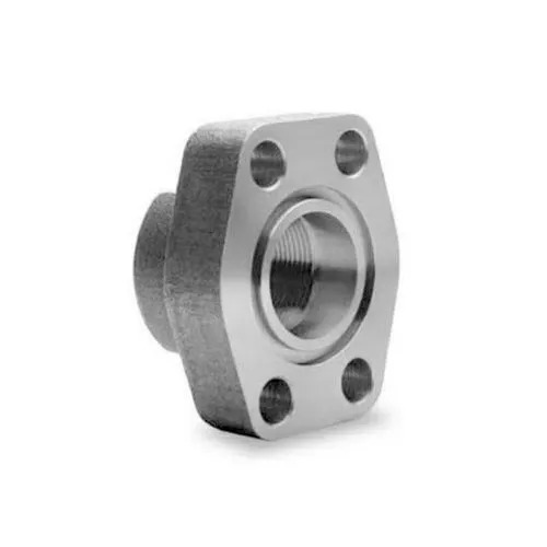
SAE Flange Range
SAE blind flanges follow the same SAE J518 / ISO 6162 standard and the same two pressure series — Code 61 (standard pressure, 3000–5000 PSI) and Code 62 (high pressure, 6000 PSI) — as flow-through SAE flanges, so a blind flange of the correct code and size bolts directly onto the standardised port it is capping.
| Feature | SAE Blind Flange | Flow-Through SAE Flange (Mono / Split) |
|---|---|---|
| Bore | Solid — no bore; closed head | Bored — passes fluid to connected pipe/hose |
| Function | Seals off / caps an unused or isolated port | Connects pipe or hose to the port for fluid flow |
| Pipe connection | None — there is no pipe-end connection | Threaded, socket weld, or butt weld pipe end |
| Bolt pattern | Standard SAE 4-bolt (Code 61 / 62) | Standard SAE 4-bolt (Code 61 / 62) |
| Seal | O-ring against port face | O-ring against port face |
| Typical use | Capping spare ports, pressure testing, decommissioning | Live hydraulic connections carrying fluid |
| Criterion | Code 61 (Standard Pressure) | Code 62 (High Pressure) |
|---|---|---|
| SAE / ISO standard | SAE J518 Code 61 / ISO 6162-1 | SAE J518 Code 62 / ISO 6162-2 |
| Pressure rating | 3000–5000 PSI (207–345 bar) — size dependent | 6000 PSI (420 bar) — all sizes |
| Flange head diameter | Larger head for same port size | Smaller, thicker head |
| Bolt size | Smaller bolts, wider spacing | Larger bolts, closer spacing |
| Interchangeable? | No — different bolt pattern from Code 62 | No — verify port code before ordering |
| Typical use | Capping medium-pressure ports on mobile hydraulics | Capping high-pressure pump/press circuit ports |
| Scenario | How the Blind Flange Is Used |
|---|---|
| Unused spare port | Pumps, motors, and manifold blocks often have multiple ports; unused ports are capped with a blind flange to retain pressure and keep contamination out |
| Pressure testing | Blind flanges cap open ports during hydrostatic / pneumatic pressure testing of a circuit or component |
| Circuit decommissioning | When a branch is taken out of service, the port is blanked off with a blind flange instead of leaving a live connection |
| Future expansion provision | A port reserved for future equipment is capped with a blind flange until the connection is made |
| Shipping & storage protection | OEM pumps and valves are shipped with blind flanges protecting the ports from dirt ingress and damage in transit |
| Maintenance isolation | During maintenance, a port can be temporarily blanked to isolate it from the rest of the pressurised system |
| Parameter | Details |
|---|---|
| Brand | TES-LOK (Tesco Steel & Engineering) |
| Size Range | 3/8" to 5" NB |
| Pressure Series | Code 61 — 3000 PSI | Code 62 — 6000 PSI |
| Working Pressure | 34 bar to 420 bar (depending on size and code) |
| Type | Blind (closed / no-bore) — mono and split clamp blanking versions |
| Sealing | O-ring against port face (NBR / Viton / EPDM) |
| Standards | SAE J518 | ISO 6162-1 (Code 61) | ISO 6162-2 (Code 62) |
| Certifications | ISO 9001:2015 | EN 10204 3.1 MTC | PMI (XRF) on request | Hydrostatic test cert |
| Material Family | Grades / ASTM Spec |
|---|---|
| Stainless Steel SAE Blind Flanges | ASTM A182 F304 / 304H / 304L / 316 / 316H / 316L / 316Ti, 309, 310, 317L, 321, 347, 904L |
| Duplex & Super Duplex Blind Flanges | ASTM A182 F51 (2205), F53 (2507), F55 (Zeron 100) |
| Alloy Steel SAE Blind Flanges | ASTM A182 F5, F9, F11, F21, F22, F91 |
| Carbon Steel SAE Blind Flanges | ASTM A105 (standard hydraulic flange material) |
| Low-Temp Carbon Steel (LTCS) | ASTM A350 LF2 — cryogenic / low-temperature service |
| Copper-Nickel SAE Blind Flanges | C70600 (90/10), C71500 (70/30), C71640 |
| Nickel SAE Blind Flanges | UNS N02200, UNS N02201 |
| Monel SAE Blind Flanges | UNS N04400, UNS N05500, Alloy 20 |
| Inconel SAE Blind Flanges | UNS N06600, N06601, N06625, N08800, N08810, N08825 |
| Hastelloy SAE Blind Flanges | UNS N10276, N06022, N10665, N06455 |
| Titanium SAE Blind Flanges | Gr. 1, Gr. 2, Gr. 3, DTH 3.7035, DTH 3.7055 |
Download the full TES-LOK SAE blind flange dimension tables for the 3000 PSI (Code 61) and 6000 PSI (Code 62) series — flange head diameter, bolt circle, bolt size, and thickness for each NB size:
📄 3000 PSI SAE Blind Flange Dimensions (PDF) 📄 6000 PSI SAE Blind Flange Dimensions (PDF) 📄 SAE Mono Flange Dimensions (PDF)| O-Ring Material | Temperature Range | Compatible Hydraulic Fluid | Avoid With |
|---|---|---|---|
| NBR (Nitrile) — Standard | −40°C to +100°C | Mineral oil hydraulic fluids (ISO HM / HV), diesel | Phosphate ester, Skydrol, hot water |
| Viton (FKM) | −20°C to +200°C | High-temperature mineral oils, fire-resistant HFD fluids | Skydrol (phosphate ester), hot water/steam |
| EPDM | −40°C to +150°C | Phosphate ester (Skydrol) fluids, water-glycol (HFC) | Mineral oils, petroleum-based fluids |
Flange head diameter, bolt circle, bolt hole size, and O-ring groove are machined to SAE J518 / ISO 6162 tolerances for Code 61 and Code 62 — so the blind flange bolts directly onto any standardised SAE port being capped.
The closed head is machined from solid stock with full wall thickness to safely retain the rated working pressure when the port is blanked — no risk of bore leakage or weld failure since there is no bore and no weld.
From standard Carbon Steel A105 to SS 316, Duplex, Inconel, Monel, and Hastelloy for corrosive and marine hydraulic systems. Single-source supply across the full alloy spectrum with EN 10204 3.1 MTC and PMI on request.
Code 62 (6000 PSI / 420 bar) blind flanges safely cap high-pressure hydraulic ports on press circuits, heavy machinery, and pump outlets where a reliable pressure-tight blank is essential for safety.
Full dimensional data for 3000 PSI and 6000 PSI blind flange series available as downloadable PDF charts — flange head OD, bolt circle, bolt size, and thickness for every NB size.
SAE blind flanges are manufactured on the same CNC machining centres and to the same QA/QC discipline that govern our full range of ASME, DIN, and EN flanges. ISO 9001:2015 certified, with material traceability and hydrostatic testing on every batch.
| Industry | Typical Use Point | Why SAE Blind Flange Preferred |
|---|---|---|
| Mobile & Construction Equipment | Capping unused pump and valve ports on excavators, loaders, cranes | Pressure-tight blank that bolts directly to the SAE port; resists vibration |
| Industrial Hydraulics | Blanking spare manifold block ports and power unit pump ports | Code 62 safely caps 6000 PSI ports; keeps contamination out of unused ports |
| Marine & Offshore | Capping spare ports on deck machinery and steering gear hydraulics | SS 316 / Duplex blind flange resists marine corrosion on exposed ports |
| Oil & Gas | Blanking ports during BOP and drilling rig hydraulic pressure testing | High-pressure pressure-tight cap for hydrostatic test isolation |
| OEM Equipment Shipping | Protecting pump, motor, and valve ports during transit and storage | Keeps dirt and damage out of ports until commissioning |
| Steel & Metals | Capping spare ports on rolling mill and casting hydraulic systems | Heavy-duty blank withstands cyclic pressure in steel plant hydraulics |
| Mining | Blanking unused ports on haul truck and shovel hydraulics | Robust cap survives shock and vibration in mining equipment |
| Wind Energy | Capping spare ports on turbine pitch/yaw hydraulic manifolds | Reliable pressure-tight blank in confined nacelle hydraulic systems |
Q1. What is an SAE blind flange used for?
An SAE blind flange is a solid, no-bore SAE J518 flange used to cap and seal an unused or isolated hydraulic port — on a pump, motor, valve, or manifold block. It bolts to the port with the standard 4-bolt SAE pattern and seals with an O-ring, retaining the port's rated pressure without allowing any flow. It is used for capping spare ports, isolating circuits during maintenance, pressure testing, decommissioning branches, and protecting ports during shipping and storage.
Q2. What is the difference between an SAE blind flange and a standard SAE flange?
A standard (flow-through) SAE flange has a bore that allows fluid to pass from the port into the connected pipe or hose. An SAE blind flange has no bore — it is a closed, solid head that simply caps and seals the port. Both use the same SAE J518 4-bolt pattern and O-ring port seal, and come in the same Code 61 / Code 62 pressure series, but the blind flange has no pipe-end connection.
Q3. What is the difference between Code 61 and Code 62 SAE blind flanges?
Code 61 is the standard-pressure series (3000–5000 PSI / 207–345 bar) and Code 62 is the high-pressure series (6000 PSI / 420 bar). For the same nominal port size, Code 62 has a smaller, thicker flange head, larger bolts, and closer bolt-hole spacing. They are not interchangeable — a Code 61 blind flange will not seal a Code 62 port and vice versa. Always confirm the code stamped on the port being capped before ordering.
Q4. Can I remove an SAE blind flange while the system is pressurised?
No — never remove a blind flange under pressure. A blind flange retains the full system pressure on the capped port. Removing it while the circuit is live can cause a sudden, dangerous release of pressurised hydraulic fluid. Always depressurise and isolate the port and connected circuit before loosening any blind flange bolts.
Q5. Do SAE blind flanges need a gasket or O-ring?
SAE blind flanges seal with an O-ring against the port face — the same sealing method as flow-through SAE flanges. The O-ring sits in the flange head groove and is compressed against the port boss when the four bolts are tightened. No separate gasket is required. Always select the O-ring elastomer (NBR, Viton, or EPDM) to match the hydraulic fluid in the system.
Q6. What material should I choose for an SAE blind flange in a marine environment?
For marine and offshore hydraulics, choose SS 316 / 316L or Duplex 2205. These resist the chloride-induced corrosion that attacks standard Carbon Steel blind flanges in salt atmospheres — especially important on exposed ports that are not protected by fluid flow. Super Duplex 2507 is available for the most aggressive seawater-adjacent service. All are supplied with EN 10204 3.1 MTC.
Q7. Are SAE blind flanges available in both mono and split blanking versions?
Yes. The mono blind flange is a single-piece solid head that bolts directly to the port. A split blanking version uses two clamp halves around a solid blind head, allowing the blanking flange to be fitted in tight spaces where a one-piece head is awkward to position. Both versions cap the port to the same SAE J518 pressure rating.
Q8. Do you provide SAE blind flange dimension charts?
Yes. Full dimension charts for the 3000 PSI (Code 61) and 6000 PSI (Code 62) blind flange series are available as downloadable PDF documents on this page. These give flange head OD, bolt circle, bolt size, bolt-hole spacing, and head thickness for every NB size. For any size or configuration not in the standard charts, contact our technical team.