

TES-LOK Integral ANSI Flange Connectors — single-piece compression tube fittings with a fully machined integral ASME B16.5 raised-face (RF) or flat-face (FF) flange end. No companion flange or stub ring needed — the complete ANSI bolt circle, gasket seating surface, and bore are machined in one body. SS 316, Duplex 2205, Inconel 625, Monel 400, Carbon Steel. Class 150 to Class 600. ISO 9001:2015 certified. Made in India.
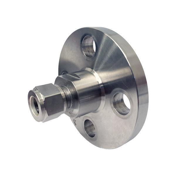
TES-LOK Integral ANSI Flange Connector
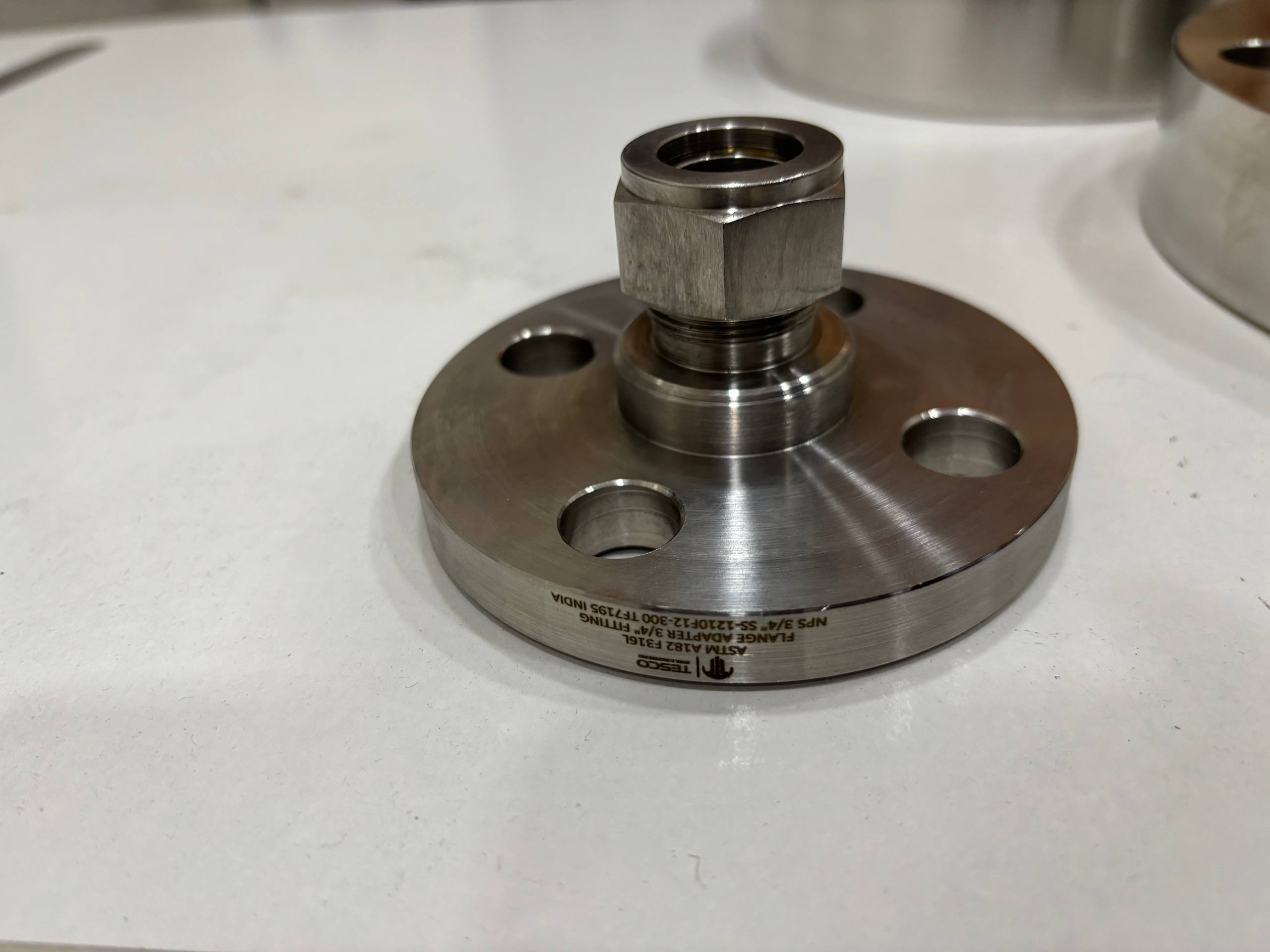
SS 316L — 3/4" Class 150 / 300

Duplex 2205 — 3/4" Flange Series
"ANSI" in this context refers to the ANSI/ASME B16.5 standard which defines the bolt circle, number of bolt holes, hole diameter, raised face diameter, gasket face finish, and pressure-temperature ratings for each flange size (NPS) and pressure class (150 through 2500). Since bolt hole positions are fixed in the integral body, tube orientation is determined at the time of order — the body cannot rotate after machining unlike a lapped-joint connector.
| Feature | Integral ANSI Flange Connector | Lapped Flange Tube Connector |
|---|---|---|
| Flange construction | Complete flange (face + bolt circle + bore) machined in one piece — no separate parts | Stub end only — requires a separate companion (backing) flange |
| Bolt hole rotation | Fixed — bolt holes cannot be rotated; tube direction set at manufacture | Free rotation before bolting — tube direction adjustable on site |
| Face type | Raised Face (RF) or Flat Face (FF) or RTJ groove — all self-contained | Flat face (lapped) typical; companion flange provides raised face if needed |
| Pressure class range | Class 150 to Class 600 standard; Class 900/1500 on special order | Class 150 and Class 300 most common |
| Companion flange | Not required — self-contained unit bolts directly to equipment nozzle flange | Required on equipment side — separate backing flange needed |
| Material savings | Entire flange body must be in the required alloy | Only stub end in expensive alloy; CS companion flange used on equipment |
| Compactness | More compact — single body, fewer parts | Slightly bulkier — stub end + companion flange stack |
| Best use | Where bolt hole alignment is known in advance; higher pressure classes; compact assemblies | Where bolt hole alignment is uncertain on site; material cost savings needed |
| Face Type | Description | Gasket Used | ASME Designation | Best For |
|---|---|---|---|---|
| Raised Face (RF) | Elevated circular seating area 1.6 mm (Class 150/300) or 6.4 mm (Class 600+) above bolt circle area | Spiral-wound, ring gasket (inner + outer guide rings) | ASME B16.5 RF | Process piping RF nozzles — most common on Class 150 to 600 instrument connections |
| Flat Face (FF) | Full flange face flush with bolt circle — no raised ring | Full-face gasket (PTFE, compressed fibre, rubber) | ASME B16.5 FF | Connections to cast iron, glass-lined, or plastic-flanged equipment — avoids flange bending moment from RF contact |
| Ring Type Joint (RTJ) | Trapezoidal groove machined into face; accepts oval or octagonal ring gasket | Soft iron, SS 316 oval or octagonal ring | ASME B16.5 RTJ | High-pressure / high-temperature service Class 600 and above; HP/HT flanged instrument nozzles on process vessels |
| Configuration | Flange End | Tube End | Application |
|---|---|---|---|
| Straight Integral Flange Connector | Full ANSI RF / FF / RTJ face — Class 150 / 300 / 600 | Double-ferrule compression — tube OD 1/4" to 1" | Most common: straight tube entry into a flanged nozzle on vessel, valve, or manifold |
| 90° Elbow Integral Flange Connector | Full ANSI RF face — Class 150 / 300 | Double-ferrule compression at 90° to flange axis | Tube must exit at right angles to the flange face — lateral space constraint |
| 45° Elbow Integral Flange Connector | Full ANSI RF face — Class 150 / 300 | Double-ferrule compression at 45° to flange axis | Diagonal tube routing from flange face — lower turbulence than 90° elbow |
| Reducing Integral Flange Connector | Full ANSI RF face — bore matched to tube OD | Smaller tube OD than flange bore | Large flange bore (1" NPS) to small instrument tube (1/4" OD) — no reducing bushing needed |
| Class 600 RTJ Integral Flange Connector | RTJ groove face — Class 600 | Double-ferrule compression — heavy-wall tube | HP/HT vessel instrument nozzles requiring Ring Type Joint seal integrity |
| Parameter | Details |
|---|---|
| Brand | TES-LOK (Tesco Steel & Engineering) |
| Tube OD Range | 1/4", 3/8", 1/2", 5/8", 3/4", 1" | Metric: 6 mm, 10 mm, 12 mm, 16 mm, 25 mm |
| Flange NPS Range | 1/2" NPS to 2" NPS |
| Flange Class | Class 150, Class 300, Class 600 (per ASME B16.5) | Class 900 / 1500 on special order |
| Flange Face Types | Raised Face (RF) — standard | Flat Face (FF) — on request | Ring Type Joint (RTJ) — Class 600 and above |
| Flange Face Finish | 125–250 AARH (3.2–6.3 μm Ra) for spiral-wound gaskets | 63–125 AARH (1.6–3.2 μm Ra) available for soft gaskets |
| Pressure Rating | Per ASME B16.5 P-T tables for each material group and Class — SS 316 Class 150: 275 PSI at 100°C; Class 300: 720 PSI; Class 600: 1440 PSI at 100°C |
| Temperature Range | SS 316: −196°C to 450°C | Carbon Steel A105: −29°C to 425°C | Inconel 625: up to 650°C | LTCS A350 LF2: −46°C to 345°C |
| Body Material | SS 304, SS 316 / 316L (A182 F316), Carbon Steel (A105), LTCS (A350 LF2), Duplex 2205 (A182 F51), Super Duplex 2507 (A182 F53/F55), Inconel 625 (B564 N06625), Monel 400 (B564 N04400), Hastelloy C-276 (B574 N10276) |
| Bolt Circle & Holes | Per ASME B16.5 for each NPS and Class — 4 bolt holes for NPS ≤ 2"; 8 bolt holes for NPS 2.5" and above |
| Body Construction | Single-piece forged or bar-machined — integral flange + tube body; no welded or press-fit flange ring |
| Standards | ASME B16.5 (flanges) | ASME B31.3 / B31.1 (piping) | ASTM A182 / A105 / B564 material specs |
| Certifications | ISO 9001:2015 | EN 10204 3.1 MTC | PMI (XRF) on request | Hydrostatic test cert | NACE MR0175 on request |
| Material | ASTM Spec | ASME Mat. Group | Class 150 @ 100°C | Class 300 @ 100°C | Class 600 @ 100°C |
|---|---|---|---|---|---|
| Carbon Steel (A105) | A105 / A182 F1 | 1.1 | 285 PSI | 740 PSI | 1480 PSI |
| SS 304 / 304L | A182 F304 / F304L | 2.1 | 275 PSI | 720 PSI | 1440 PSI |
| SS 316 / 316L | A182 F316 / F316L | 2.2 | 275 PSI | 720 PSI | 1440 PSI |
| Duplex 2205 | A182 F51 | 3.1 | 415 PSI | 1075 PSI | 2160 PSI |
| Super Duplex 2507 | A182 F53 / F55 | 3.2 | 430 PSI | 1120 PSI | 2245 PSI |
| Inconel 625 | B564 N06625 | 4.2 | 290 PSI | 750 PSI | 1500 PSI |
| Monel 400 | B564 N04400 | 4.1 | 230 PSI | 600 PSI | 1200 PSI |
| Hastelloy C-276 | B574 N10276 | 4.2 | 230 PSI | 600 PSI | 1200 PSI |
| NPS | Tube OD (Typical) | Class 150 BC (mm) | Class 300 BC (mm) | No. Bolts | Bolt Dia. | Raised Face Dia. (mm) |
|---|---|---|---|---|---|---|
| 1/2" | 1/4" / 6 mm | 60.3 | 66.7 | 4 | M12 | 34.9 |
| 3/4" | 3/8" / 10 mm | 69.9 | 82.6 | 4 | M12 | 42.9 |
| 1" | 1/2" / 12 mm | 79.4 | 88.9 | 4 | M14 | 50.8 |
| 1-1/4" | 5/8" / 16 mm | 88.9 | 98.4 | 4 | M14 | 63.5 |
| 1-1/2" | 3/4" / 20 mm | 98.4 | 114.3 | 4 | M16 | 73.0 |
| 2" | 1" / 25 mm | 120.7 | 127.0 | 4 / 8 | M16 | 92.1 |
The flange ring is not welded, pressed, or threaded onto a separate tube body — it is machined from the same forged or bar-stock billet as the compression end. No heat-affected zone at a flange-to-body weld, no intermediate joint that can leak, loosen, or crack under thermal cycling. The single-piece construction is the strongest and most reliable configuration for flanged instrument connections.
Raised face diameter, bolt circle, hole count, hole diameter, face finish, and flange OD are all machined to ASME B16.5 tolerances for each NPS and Class. The connector bolts to any ASME B16.5-compliant nozzle flange on process equipment — no dimensional mismatches, no modification required on site.
Integral flange connectors are the natural choice for Class 600 and above service — the single-piece body can withstand the higher bolt loads at Class 600 without flange ring separation, and RTJ grooves can be machined into the integral face for high-integrity ring gasket sealing on HP/HT reactor and turbine instrument nozzles.
All nine body materials available — from Carbon Steel A105 (budget) to Super Duplex 2507 (offshore corrosion) to Inconel 625 (HP/HT). NACE MR0175 / ISO 15156 hardness compliance and Positive Material Identification (PMI by XRF) available for all alloy grades. EN 10204 3.1 material test certificates for every batch.
As with all TES-LOK flange connectors, the compression tube end can be disconnected and reconnected for maintenance — gauge replacement, transmitter calibration, instrument loop testing — without breaking the flanged gasket seal on the process side. Hot-work permit not needed for instrument maintenance.
Tesco Steel & Engineering is an established manufacturer of ASME B16.5 flanges in all materials. Integral ANSI flange connectors are an extension of this core capability — the same machining centres, the same gauging, and the same ASME dimensional inspection protocols that govern our full-size ASME flanges are applied to every flange connector we manufacture.
| Industry | Typical Use Point | Why Integral ANSI Flange Connector Preferred |
|---|---|---|
| Oil & Gas — Upstream | HP wellhead instrument nozzle connections — Class 600 raised face nozzles on ANSI flanged Christmas trees and wellheads | Class 600 RTJ integral connector handles HP/HT conditions; single-piece body withstands wellhead vibration without joint failure |
| Petrochemical / Refinery | Reactor instrument nozzles; distillation column temperature tap flanged connections; HDS unit pressure instrument flanged connections | Class 300 / 600 integral flange connector in SS 316 or Inconel 625 for corrosive and HP process instrument nozzles; no intermediate coupling |
| Power Generation | HP steam drum flanged instrument nozzles; HP turbine inlet temperature measurement flanged connections per ASME B31.1 | ASME B31.1 power piping requires flanged instrument connections on Class IV steam — integral ANSI connector satisfies this requirement compactly |
| Offshore / FPSO | Subsea production manifold instrument flanged nozzles; topsides HP separator instrument connections | Super Duplex 2507 Class 600 integral flange connector with NACE MR0175 compliance — corrosion resistant for subsea and topsides chloride environment |
| LNG / Cryogenic | LNG process vessel Class 150 instrument flanged nozzles; liquid nitrogen storage vessel instrument flanges | LTCS A350 LF2 integral connector impact-tested to −46°C; Class 150 flanged connection performs reliably in cryogenic thermal cycling |
| Chemical Processing | Hastelloy C-276 reactor vessel flanged instrument nozzles on acid and halogen service | Hastelloy Class 150 integral flange connector in one piece — no dissimilar metal weld between flange ring and body; full corrosion resistance throughout |
| Pharmaceutical / Biotech | SS 316L bioreactor vessel flanged instrument nozzles for temperature and pressure measurement on sterile/WFI loops | Flat-face SS 316L integral connector with PTFE full-face gasket — cleanable, no crevice between flange ring and body; suitable for CIP/SIP service |
| Nuclear | Safety-class instrument nozzle flanged connections on primary coolant systems and safety injection lines | Full ASME NQA-1 documentation; EN 10204 3.1 MTC; PMI per ASME nuclear code requirements; single-piece body provides highest mechanical integrity |
Q1. What is the key difference between an integral ANSI flange connector and a lapped flange tube connector?
The integral ANSI flange connector has the complete ANSI flange — raised face, bolt circle, and bore — machined in one piece with the tube compression body. No companion flange is needed. The lapped flange connector has only a flat-face stub end in the tube body; a separate companion (backing) flange on the equipment side carries the full bolt circle. The integral design is more compact and self-contained; the lapped design allows free rotation for bolt-hole alignment and material cost savings (CS companion flange with alloy stub end). The integral design is typically preferred for Class 300 and above where lapped connections may not be rated.
Q2. Why must I specify tube exit direction when ordering an integral ANSI flange connector?
Because the bolt holes in the integral flange are machined at fixed angular positions relative to the tube compression axis. The tube can exit at 0° (axial, same direction as flange bore), 90°, 45°, or another specified angle — but this angle is set during machining and cannot be changed on site. When ordering, specify the flange NPS, Class, face type, tube OD, and the required angular relationship between the tube exit direction and the bolt-hole pattern (e.g. "tube at 90° to flange axis with tube pointing toward bolt hole #1" or "tube at 12 o'clock position when flange is vertical with bolt holes at 3, 6, 9, 12 o'clock positions").
Q3. What is the face finish required on a raised-face integral flange connector?
Per ASME B16.5, the raised face surface finish must be within 125–250 AARH (3.2–6.3 μm Ra) for spiral-wound gaskets — a phonograph or concentric groove finish produced by specific tool radius and feed rate during face machining. A finer finish (63–125 AARH / 1.6–3.2 μm Ra) is required for soft gaskets (PTFE, rubber) to prevent gasket extrusion. TES-LOK machines the standard 125–250 AARH raised face finish and can supply 63–125 AARH on request.
Q4. Can an integral ANSI flange connector be used at Class 600 with an RTJ gasket?
Yes — this is one of the specific applications for integral flange connectors. The RTJ groove (trapezoidal cross-section per ASME B16.20) is machined directly into the integral flange face. Class 600 RTJ integral connectors are available in SS 316, Duplex 2205, Inconel 625, and Carbon Steel. Specify the ring type (oval or octagonal) and ring material (soft iron, SS 316, or low-alloy steel) when ordering.
Q5. How is the flange bore sized relative to the tube OD?
The flange bore is matched to the tube OD — for a 1/2" OD tube, the flow bore through the integral flange connector is equal to the instrument tube's inner diameter, with a smooth transition from the tube compression end through the body bore to the flange face. There is no restriction or step change in bore. This maintains full flow capacity through the fitting and eliminates dead-leg volume at the instrument nozzle entry.
Q6. Are TES-LOK integral flange connectors PED (Pressure Equipment Directive) compliant?
TES-LOK integral ANSI flange connectors manufactured for European CE-marked pressure equipment can be supplied with PED 2014/68/EU conformity documentation for the relevant Category and Module of Assessment. Material test certificates per EN 10204 3.1, hydrostatic test certification, and dimensional inspection reports are provided. The flange dimensions per ASME B16.5 are also cross-referenced to EN 1759-1 (ASME-standard flanges recognised in European piping). Contact TES-LOK's export team for PED-specific documentation packages.
Q7. What studs and bolts should be used with a Class 300 SS 316 integral flange connector?
Per ASME B16.5 and ASME B31.3, Class 300 bolted flange joints use fully threaded studs to ASTM A193 B7 (alloy steel, standard service) or A193 B8M (SS 316, corrosion service) with A194 Grade 2H (standard) or A194 Grade 8M (SS) heavy hex nuts. For cryogenic service (LTCS body), A320 L7 studs with A194 Grade 4 nuts are used. For high-temperature service above 450°C, A193 B16 chrome-moly studs are specified. TES-LOK can supply matching stud-bolt sets for each connector material and class on request.
Q8. Can TES-LOK supply the integral flange connector together with the matching equipment nozzle flange?
Yes. Tesco Steel & Engineering is a full-scope ASME B16.5 flange manufacturer in addition to tube fittings. We can supply the integral ANSI flange tube connector and the matching equipment-side weld-neck or socket-weld companion flange as a matched pair — same NPS, same Class, same material (or dissimilar material pair if specified) — with co-ordinated inspection reports and matching material certifications. This simplifies procurement and ensures full dimensional compatibility between the two flange halves.