

TES-LOK Flange Lapped Tube Connectors — double-ferrule compression tube fittings with an integral lapped flange end for direct bolted connection of instrument tubing to flanged equipment nozzles, flanged instrument bodies, and flanged manifolds. SS 316, Duplex, Inconel, Carbon Steel. ASME B16.5 Class 150 / 300. ISO 9001:2015 certified. Made in India.
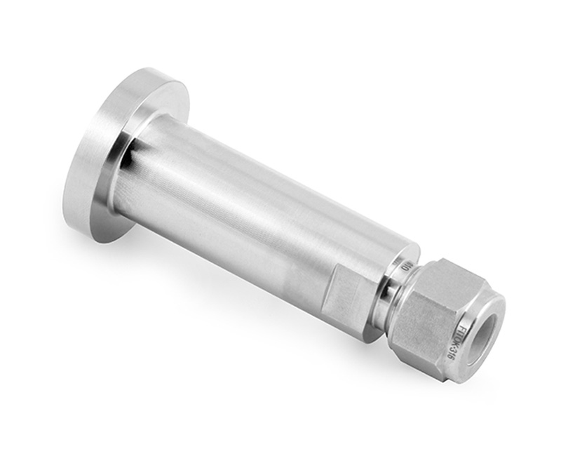
TES-LOK Flange Lapped Tube Connector
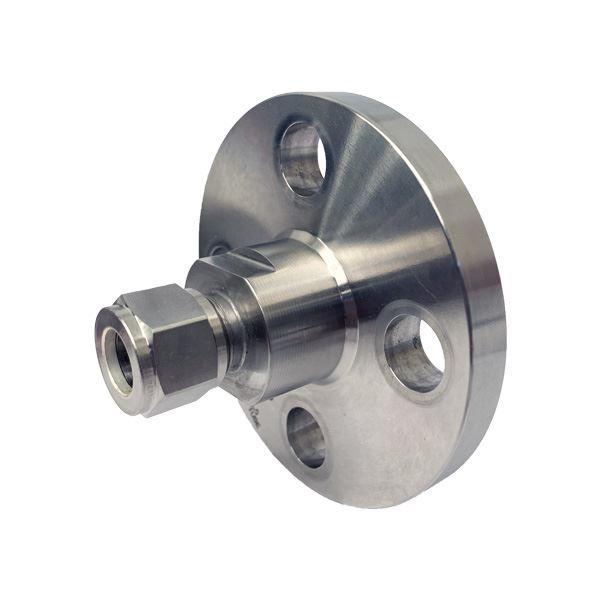
Integral Flange Connector (Related)
Flange Adapter — Related Series
This fitting is the instrument-tubing-world equivalent of a lapped joint stub end in pipe flange systems — it brings the bolted flange connection technology into the instrument tube fitting domain, allowing engineers to use standard gasketed flanged connections at the process equipment interface while retaining the compression tube fitting on the instrument side for easy maintenance access.
| Feature | Flange Lapped Tube Connector | Integral Flange Tube Connector |
|---|---|---|
| Flange type | Flat-face lapped stub — mates with companion flange; bolt holes in connector body | Full integral raised-face flange — all bolt holes and gasket seating in connector body |
| Bolt rotation | Connector can rotate to align bolt holes before final tightening (lapped principle) | Fixed bolt hole positions — bolt alignment set at manufacture |
| Gasket type | Full-face flat gasket typical; can use spiral-wound or ring gasket | Raised-face spiral-wound, ring, or full-face gasket depending on face type |
| Flange dimensions | Matches companion flange per ASME B16.5 or DIN/EN 1092 bolt circle | Self-contained per ASME B16.5 — no companion flange needed |
| Material savings | Only connector body in expensive alloy; Carbon Steel companion flange on equipment | Entire flange ring in same material as connector body |
| Installation flexibility | High — can rotate freely to align during bolting | Lower — bolt holes are fixed at manufacture |
| Best use | Where bolt hole alignment is uncertain until final assembly; dissimilar material combination savings | Where a self-contained flanged unit is preferred; higher pressure classes |
| Configuration | Flange End | Tube End | Application |
|---|---|---|---|
| Standard Lapped Flange Connector (Straight) | Flat-face lapped stub — ASME B16.5 Class 150 / 300 bolt circle | Double-ferrule compression — tube OD 1/4" to 1" | Instrument tube to flanged vessel nozzle or flanged valve bonnet — most common configuration |
| Lapped Flange Elbow Connector (90°) | Flat-face lapped stub flange | Double-ferrule compression at 90° to flange axis | Where tube exits at right angle to the flange face — lateral space constraint |
| Lapped Flange Elbow Connector (45°) | Flat-face lapped stub flange | Double-ferrule compression at 45° to flange axis | Diagonal tube routing from flanged nozzle — lower pressure drop than 90° |
| Reducing Lapped Flange Connector | Larger flange face bore | Smaller tube OD compression | Large flanged nozzle bore to small instrument tube — eliminates reducing bushing in the flow path |
| DIN / EN 1092 Lapped Flange Connector | Flat-face per DIN 2501 / EN 1092 PN 10/16/40 | Double-ferrule compression — metric tube OD | European metric flanged equipment with metric instrument tubing |
| Parameter | Details |
|---|---|
| Brand | TES-LOK (Tesco Steel & Engineering) |
| Tube OD Range | 1/4", 3/8", 1/2", 5/8", 3/4", 1" | Metric: 6 mm, 8 mm, 10 mm, 12 mm, 16 mm, 25 mm |
| Flange Size (NPS) | 1/2" NPS to 2" NPS (ASME B16.5) | DN 15 to DN 50 (DIN / EN 1092) |
| Flange Class | Class 150 (PN 20) and Class 300 (PN 50) per ASME B16.5 | PN 10, PN 16, PN 25, PN 40 per DIN / EN 1092 |
| Flange Face Type | Flat Face (FF) — standard for lapped connector | Raised Face (RF) option available |
| Flange Face Finish | 125–250 AARH (3.2–6.3 μm Ra) machined face — suitable for spiral-wound and soft gaskets |
| Pressure Rating | Per ASME B16.5 Class 150 / 300 for the body material and temperature — SS 316 Class 150: 275 PSI at 100°C; Class 300: 720 PSI at 100°C |
| Temperature Range | SS 316: −196°C to 450°C | Carbon Steel: −29°C to 425°C | Inconel 625: up to 650°C |
| Body Material | SS 304, SS 316 / 316L, Carbon Steel (A105), LTCS (A350 LF2), Duplex (A182 F51), Super Duplex (A182 F53), Inconel 625 (B564), Monel 400 (B564), Hastelloy C-276 |
| Ferrule Material | Matched to body material |
| Bolt Circle & Bolt Holes | Per ASME B16.5 Table dimensional requirements for each NPS and Class — 4 holes for NPS ≤ 2" |
| Standards | ASME B16.5 (flanges) | DIN 2501 / EN 1092-1 (metric flanges) | ASME B31.3 (piping) |
| Certifications | ISO 9001:2015 | EN 10204 3.1 MTC | PMI (XRF) on request | Hydrostatic test cert |
| Material | ASTM Spec | ASME B16.5 Class 150 P-T Rating (100°C) | Corrosion Service | Application |
|---|---|---|---|---|
| Carbon Steel (A105) | A105 / A182 F1 | 285 PSI | Low — coating needed | General refinery, oil & gas wellhead nozzles |
| SS 304 / 304L | A182 F304 | 275 PSI | Good | Food, pharma, water — flanged vessel instrument nozzles |
| SS 316 / 316L | A182 F316 | 275 PSI | Excellent — chloride resistant | Chemical, offshore, marine flanged instrument connections |
| Duplex 2205 | A182 F51 | 415 PSI | Superior — pitting / SCC | Seawater, chloride-rich process streams, FPSO instrument nozzles |
| Super Duplex 2507 | A182 F53/F55 | 430 PSI | Outstanding — PREN >40 | Subsea instrument nozzles, highly aggressive chloride streams |
| Inconel 625 | B564 N06625 | 290 PSI | Outstanding — high-temp & acids | HP/HT reactor nozzle connections; fired heater instrument access |
| Monel 400 | B564 N04400 | 230 PSI | Excellent — HF, seawater | HF alkylation unit vessel nozzles; desalination instrument connections |
| Hastelloy C-276 | B574 N10276 | 230 PSI | Superior — strong acids | Chemical reactor flanged instrument nozzles; FGD system connections |
| Gasket Type | Material | Temperature Limit | Pressure Limit | Best Suited For |
|---|---|---|---|---|
| Full-Face Soft Gasket | PTFE (white or filled) | 260°C | Class 150 max | Low-pressure chemical service; flat-face flange with flanged plastic or glass equipment |
| Full-Face Soft Gasket | Compressed fibre (CAF / Klingersit) | 400°C | Class 150 / 300 | Steam, water, and general service; cost-effective option |
| Spiral-Wound Gasket | SS 316 winding + graphite filler | 450°C | Class 150 to 1500 | High-temp steam, oil & gas process nozzles; preferred for Class 300 lapped connections |
| Ring Type Joint (RTJ) | Soft iron or SS 316 | 700°C | Class 600 and above | HP/HT service; requires RTJ groove machined in flange face — not standard for lapped connectors |
| Kammprofile Gasket | Core metal + graphite facing | 450°C | Class 150 to 900 | High-cycle flange joints; better re-usability than spiral-wound |
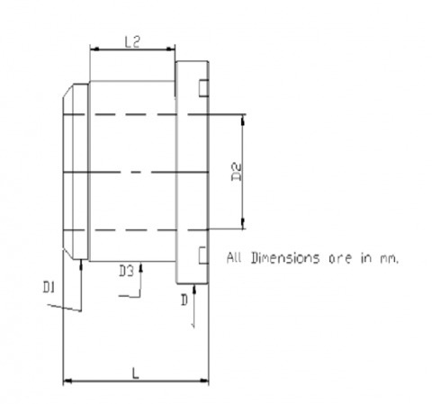
The lapped flange face dimensions — bolt circle diameter, bolt hole count, hole diameter, flange OD, and face finish — are machined to ASME B16.5 tolerances for each NPS and Class. This ensures the TES-LOK connector mates correctly with any ASME B16.5-compliant companion flange, regardless of the companion flange's origin or manufacturer.
Available in 9 body materials from Carbon Steel A105 to Hastelloy C-276, with NACE MR0175 / ISO 15156 hardness compliance for sour service (H₂S) vessel instrument nozzle connections. Duplex 2205 and Super Duplex 2507 are available with full EN 10204 3.1 MTC and PMI certification.
The lapped design allows the connector body to rotate freely relative to the mating companion flange during bolt-up. This means the installer can set the tube exit direction after aligning the bolt holes — a critical advantage in tight equipment spaces where the tube must exit in a specific direction that is unknown until the nozzle orientation is confirmed on-site.
Eliminates the need for a half-coupling threaded into the nozzle + a separate male connector on the tube — replacing a two-piece, two-joint assembly with a single-body, single-gasketed connection. Reduces potential leak points from 3 (weld + thread + compression) to 2 (gasket + compression).
The compression tube end is never disturbed by tightening the flange bolts. Instruments can be disconnected and reconnected on the tube side without breaking the flange gasket seal — reducing both maintenance time and the risk of gasket damage from repeated opening and re-seating of the flanged joint.
Full material traceability to mill certificate. PMI by XRF available on request for all alloy grades. Hydrostatic test to 1.5× rated pressure with test report. Dimensional inspection per ASME B16.5 bolt-circle tolerances. Suitable for nuclear, defence, and offshore operator QA requirements.
| Flange NPS | Tube OD (Typical) | Class 150 Bolt Circle (mm) | Class 300 Bolt Circle (mm) | Bolt Size | No. of Bolts |
|---|---|---|---|---|---|
| 1/2" | 1/4" / 6 mm | 60.3 mm | 66.7 mm | M12 / 1/2" | 4 |
| 3/4" | 3/8" / 8 mm | 69.9 mm | 82.6 mm | M12 / 1/2" | 4 |
| 1" | 1/2" / 12 mm | 79.4 mm | 88.9 mm | M14 / 5/8" | 4 |
| 1-1/4" | 5/8" / 16 mm | 88.9 mm | 98.4 mm | M14 / 5/8" | 4 |
| 1-1/2" | 3/4" / 20 mm | 98.4 mm | 114.3 mm | M16 / 5/8" | 4 |
| 2" | 1" / 25 mm | 120.7 mm | 127.0 mm | M16 / 5/8" | 4 or 8 |
| Industry | Typical Use Point | Why Flange Lapped Connector Preferred |
|---|---|---|
| Oil & Gas / Upstream | Wellhead and production vessel instrument nozzle connections; HP/HT separator tapping points | Bolted flanged connection on process side with removable tube on instrument side; NACE MR0175 compliant alloys available |
| Petrochemical / Refinery | Reactor vessel temperature & pressure instrument nozzles; column instrument connections | Eliminates half-coupling thread in corrosive vessel nozzle; lapped design survives thermal cycling without thread loosening |
| Power Generation | HP steam drum instrument nozzle connections; turbine casing instrument tapping points | ASME B31.1 flanged instrument connections comply with power piping code requirements; no threaded joint on HP steam side |
| LNG / Cryogenic | LNG tank instrument nozzle connections; liquid nitrogen storage vessel instrument access points | LTCS A350 LF2 lapped connector withstands −46°C impact temperature; gasketed flange seal is more reliable at cryogenic temperatures than threaded joints |
| Pharmaceutical / Biotech | Bioreactor flanged instrument nozzles; autoclaved vessel instrument connections; sterile filter housing connections | SS 316L lapped connector with PTFE gasket — fully cleanable flanged joint; no thread-root crevices in contact with sterile fluid |
| Chemical Processing | Flanged reactor nozzle instrument tapping points; acid / solvent vessel temperature measurement connections | Hastelloy C-276 or Monel 400 lapped connector for aggressive chemical vessel nozzles — highest corrosion resistance in one-piece body |
| Subsea / Offshore | Subsea instrument hub connections; topside flanged manifold instrument entries on offshore platforms | Super Duplex 2507 lapped connector provides PREN >40 chloride resistance; bolted connection resists vibration better than threaded on wave-loaded topsides |
| Nuclear | Safety-class instrument nozzle connections on reactor pressure vessel and primary coolant loop flanged ports | Full material traceability, EN 10204 3.1 MTC, PMI, and ASME NQA-1 documentation available; flanged connection preferred on safety-class lines |
Q1. What is the difference between a flange lapped tube connector and an integral flange tube connector?
A flange lapped tube connector uses a stub-end lapped flange design — the connector body has a flat-face flange end that slides against a separate companion (backing) flange on the equipment. The connector body can rotate relative to the companion flange for bolt hole alignment, and only the connector body needs to be in expensive alloy while the companion flange can be Carbon Steel. An integral flange tube connector is a self-contained unit where the full flange ring — including the raised face and all bolt holes — is machined into the connector body itself. The integral design is more compact and self-contained; the lapped design is more flexible and cost-efficient for expensive alloy connectors on Carbon Steel equipment.
Q2. What ASME standard governs the flange end of a lapped tube connector?
The flange end dimensions — bolt circle diameter, hole count and diameter, flange face OD, and face finish — are governed by ASME B16.5 "Pipe Flanges and Flanged Fittings" for inch NPS sizes and Class 150 through Class 2500. For metric sizes, DIN 2501 / EN 1092-1 governs for PN-rated flanges. The compression tube end of the connector is not governed by ASME B16.5 — it follows the instrument tube fitting standards for that end.
Q3. Can a flange lapped tube connector be used on a raised-face companion flange?
Yes, with the correct gasket selection. When the connector's flat-face lapped end mates with a raised-face companion flange, a full-face gasket is normally used — it covers the full flange face and allows the flat-face connector to bear evenly against the raised-face flange without rocking. Alternatively, a spiral-wound gasket sized to the raised-face OD can be used if the flat-face connector is rated for the resulting concentrated gasket seating load. Consult TES-LOK or the gasket manufacturer for the specific combination.
Q4. Why would I choose a lapped flange tube connector over a standard male connector with BSPT thread?
A BSPT male connector screws into a threaded half-coupling on the nozzle — the thread is a potential leak point, it can loosen under vibration or thermal cycling, it creates a dead-leg thread crevice in the flow path, and it limits the nozzle boss material to threaded-quality alloy. A lapped flange tube connector uses a gasketed bolted joint that cannot loosen under vibration, has no dead-leg thread crevice, and allows the nozzle boss/companion flange to be Carbon Steel while only the tube connector body is in expensive alloy. For high-integrity, high-temperature, or corrosive service, the flanged lapped connector is the superior choice.
Q5. Do the tube connector's flange bolt holes have to align with the companion flange holes before tightening?
Yes — the bolt holes must align for the bolts to insert. But the lapped principle allows the connector body to be rotated to achieve alignment before the bolts are tightened. This is the key operational advantage: the tube exit direction is set by rotating the connector body after the gasket is in place but before the bolts are torqued. Once the bolt pattern aligns and the tube exit direction is correct, the bolts are tightened in a cross-bolt sequence to the target torque.
Q6. What bolt torque should I use for an SS 316 Class 150 lapped tube connector?
Bolt torque depends on the gasket type, gasket seating stress, bolt material, and bolt diameter. As a general guide for an SS 316 Class 150, 1" NPS lapped connector with a compressed fibre gasket and M14 A193 B8M studs, a target bolt torque of approximately 50–65 Nm is typical. For spiral-wound gaskets, higher seating stress is required — typically 70–90 Nm for the same size. Always refer to the gasket manufacturer's recommended bolt stress (m and y values per ASME Section VIII Appendix 2) and calculate the correct bolt torque from the actual bolt and lubricant combination used on site.
Q7. Are TES-LOK lapped tube connectors available in Duplex 2205 for offshore service?
Yes. Duplex 2205 (A182 F51) and Super Duplex 2507 (A182 F53/F55) lapped tube connectors are available with ASME B16.5 Class 150 and Class 300 flange ends. These are supplied with EN 10204 3.1 material test certificates, PMI by XRF, and NACE MR0175 / ISO 15156 hardness compliance certificates. For subsea service with cathodic protection, contact TES-LOK's technical team regarding CP-compatible alloy recommendations for the connector body.
Q8. Can the flange lapped tube connector be used in vacuum service?
Yes. The bolted gasket seal on the flange end is well-suited to vacuum service — provided the correct gasket is selected. For vacuum down to 10⁻³ mbar, use a PTFE or spiral-wound SS 316/graphite gasket and ensure the flange face finish is within 63–125 AARH (1.6–3.2 μm Ra) for the gasket type specified. For high-vacuum service below 10⁻³ mbar, a metal O-ring or knife-edge (CF) flange seal is recommended instead of a standard gasketed connection — contact TES-LOK for custom high-vacuum flange tube connector configurations.