

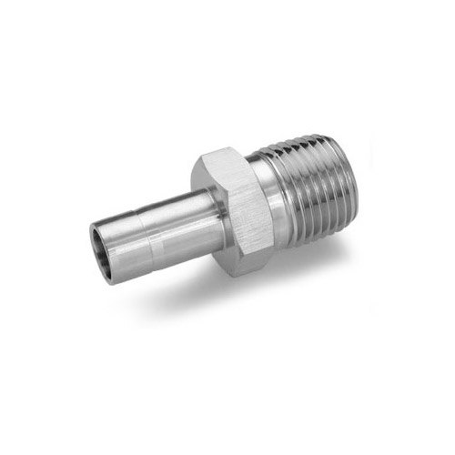
TES-LOK Weld Adapters — instrument tube compression fittings with socket-weld or butt-weld process ends for permanent, zero-leak integration of instrument tubing into welded pipelines, pressure vessels, and manifolds. SS 316, Duplex, Inconel, Carbon Steel. Up to 6000 PSI. ASME B16.11 / ASME B31.3. ISO 9001:2015 certified. Made in India.
TES-LOK Weld Adapter
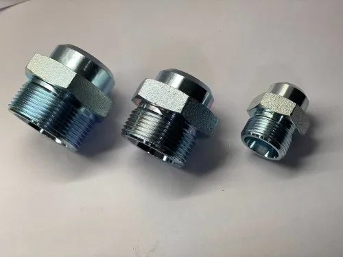
Tube Adapter Range
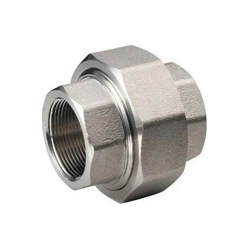
Socket Weld Union (Related)
Weld adapters are the standard solution when ASME B31.3 / B31.1 process piping specifications require all process-side connections to be welded, but the instrumentation side must remain accessible for gauge replacement, transmitter calibration, and routine instrument loop maintenance.
| Criterion | Socket Weld (SW) End | Butt Weld (BW) End |
|---|---|---|
| Joint geometry | Counter-bore socket; pipe or stub end slips inside; fillet weld on outside | Plain bore or bevelled face; pipe/stub butts end-to-end; full-penetration butt weld |
| ASME standard | ASME B16.11 socket weld fittings | ASME B16.9 butt weld fittings; pipe prep per ASME B31.3 |
| Weld type | Fillet weld — welder skill level lower; no bevel preparation required | Full-penetration groove weld — requires qualified welder; bevel prep needed |
| Weld inspection | Visual + PT/MT; RT not practical on fillet weld | Full RT / UT / PT possible on butt weld |
| Crevice concern | Annular crevice between bore and pipe OD — may trap fluid; not ideal for crevice-corrosion service | No crevice — full bore continuity; preferred for corrosive and sanitary services |
| Pressure rating | Rated per ASME B16.11 schedule — Class 3000 / 6000 / 9000 | Rated by pipe schedule and weld quality — typically higher than socket weld |
| Pipe size limit | Usually up to 2" NPS for instrumentation adapters | Any size — no upper limit; most common up to 1" NPS for instrument adapters |
| Best use | General process instrumentation; lower alloy service; where RT is not required | High-integrity service; HP/HT applications; fully radiographable joints; sanitary/pharma |
| Type | Tube End | Weld End | Application |
|---|---|---|---|
| Socket Weld Adapter (SWA) | Double-ferrule compression (tube OD) | Counter-bore socket — ASME B16.11 Class 3000/6000 | Most common: instrument tube to welded pipeline tapping point |
| Butt Weld Adapter (BWA) | Double-ferrule compression | Plain-bore BW end or bevelled BW end; schedule matches connecting pipe | High-integrity / HP-HT service; pharma / food where RT is mandatory |
| Reducing Weld Adapter | Smaller tube OD compression | Larger socket or butt-weld bore | 1/4" instrument tube on a 1/2" SW tapping boss or 3/4" BW stub |
| Weld Nipple Adapter | Double-ferrule compression | Short plain pipe-end stub (no socket) — butt-welded or set-in welded to vessel wall | Direct weld to vessel nozzle stub; commonly used on vessel instrument tappings |
| Weld-In Boss Adapter | Double-ferrule compression | External boss profile — plug-welded into a drilled hole in pipe wall or vessel | Field-welded instrument connection point added to existing line without hot-tapping |
| SW Female Adapter | Female tube end (accepts male pipe thread) | Socket weld end | Connects threaded pipe spool to welded line via socket weld at one end, female thread at other |
| Parameter | Details |
|---|---|
| Brand | TES-LOK (Tesco Steel & Engineering) |
| Tube OD Range (Compression End) | 1/4", 3/8", 1/2", 5/8", 3/4", 1" | Metric: 6 mm, 8 mm, 10 mm, 12 mm, 16 mm, 25 mm |
| Weld End Size Range | 1/8" NPS to 1" NPS (socket weld) | 1/4" NPS to 1" NPS (butt weld) |
| Socket Weld Class | Class 3000 and Class 6000 per ASME B16.11 |
| Butt Weld Schedule | Sch 40, Sch 80, Sch 160, XXH — per ASME B36.10 / B36.19 |
| Pressure Rating | Up to 6 000 PSI (SS 316, Class 6000 SW) | Rated per weld class and pipe schedule for BW end |
| Temperature Range | SS 316: −196°C to 450°C | Carbon Steel: −29°C to 425°C | LTCS: −46°C to 345°C | Inconel 625: up to 650°C |
| Body Material | SS 304, SS 316 / 316L, Carbon Steel (A105 / 1018), LTCS (A350 LF2), Duplex (A182 F51), Super Duplex (A182 F53/F55), Inconel 625, Monel 400, Hastelloy C-276, Titanium Gr. 2 |
| Ferrule Material | Matched to body: SS 316 ferrules with SS body; Carbon Steel ferrules with CS body |
| Surface Finish | Passivated (SS); phosphate or primer coated (CS); as-machined (special alloys) |
| Standards | ASME B16.11 (SW fittings) | ASME B31.3 (process piping) | ASTM A182 / A105 / B564 material specs |
| Certifications | ISO 9001:2015 | EN 10204 3.1 MTC | PMI (Positive Material Identification) on request | Hydrostatic test certification |
| Material | ASTM Spec | Temp Range | Corrosion Service | Typical Application |
|---|---|---|---|---|
| Carbon Steel | A105 / A182 F11 | −29°C to 425°C | Low — coating required | Oil & gas wellheads, general refinery lines |
| LTCS (A350 LF2) | A350 LF2 | −46°C to 345°C | Low — coating required | LNG, cryogenic service, cold utility lines |
| SS 304 / 304L | A182 F304/F304L | −196°C to 450°C | Good — general corrosion | Food, pharma, water treatment, mild chemicals |
| SS 316 / 316L | A182 F316/F316L | −196°C to 450°C | Excellent — chloride resistant | Offshore, chemical processing, marine instrument lines |
| Duplex 2205 | A182 F51 | −50°C to 315°C | Superior — pitting / SCC resistant | Seawater, chloride-rich chemical streams, offshore topsides |
| Super Duplex 2507 | A182 F53/F55 | −50°C to 300°C | Outstanding — PREN >40 | Subsea, highly corrosive chloride streams, FPSO instrument lines |
| Inconel 625 | B564 N06625 | −196°C to 650°C | Outstanding — oxidation & pitting | Fired heaters, sour gas service, HCl & H₂S streams |
| Monel 400 | B564 N04400 | −100°C to 480°C | Excellent — HF, seawater | HF alkylation units, desalination, marine offshore |
| Hastelloy C-276 | B564 N10276 | −196°C to 500°C | Superior — strong acids | Chemical reactors, acid gas scrubbing, FGD units |
| Criterion | Weld Adapter | Threaded Adapter (NPT / BSPT) |
|---|---|---|
| Leak potential | Lowest — fused metal joint; no thread loosening | Higher — thread compound can degrade; threads loosen under vibration |
| Vibration resistance | Excellent — welded joint cannot loosen | Poor to moderate — vibration loosens threaded joints over time |
| High temp / high pressure | Preferred — ASME B31.3 requires welded on HP/HT lines | Limited to Class 3000 socket or 6000 screwed at lower temperatures |
| Corrosive service | Better — no thread-to-thread crevice; smooth bore path | Thread roots create crevice — SCC and pitting initiation sites in chloride service |
| Sanitary / pharmaceutical | Required — butt-weld end gives smooth bore; no dead-leg crevice | Not acceptable — threaded connections trap product in roots |
| Reversibility | Permanent process side; compression tube side removable | Both ends removable — preferred for temporary or test connections |
| Code compliance | ASME B31.3 Category M / HP service; NACE MR0175 sour service | ASME B31.3 limited to Class I / normal fluid service |
| Installation skill | Qualified welder + PWHT (for CS if required); higher installation cost | Any fitter; lower installation cost |
TES-LOK socket weld adapters are manufactured to ASME B16.11 socket weld fittings dimensions — Class 3000 for standard service and Class 6000 for high-pressure service. Bore tolerances and socket depth meet ASME requirements, ensuring the fitting passes ASME code compliance checks and third-party inspection.
Duplex 2205 and Super Duplex 2507 weld adapters with NACE MR0175 / ISO 15156 hardness compliance are available for sour service (H₂S) instrument lines. Carbon Steel A105 and Inconel 625 grades cover the full spectrum from standard oil & gas to highly corrosive process streams.
Every heat is tracked from mill certificate to finished adapter. EN 10204 3.1 material test certificates and Positive Material Identification (PMI by XRF) are available for all alloy grades — satisfying the documentation requirements of EPC contractors, offshore operators, and ASME code projects.
The compression tube end on the instrument side allows gauges, transmitters, and other instruments to be disconnected, calibrated, and reconnected without disturbing the welded joint on the process side — reducing planned maintenance time and eliminating the need for hot-work permits to change instruments.
TES-LOK supplies both socket weld (ASME B16.11) and butt weld (schedule-matched) variants with the same compression tube end geometry and the same ferrule system — a single catalogue covers both the socket weld preference of US/API projects and the butt weld preference of European/ASME B31.3 high-integrity projects.
SS 316 and Carbon Steel (A105) socket weld adapters in Class 3000 and Class 6000 are maintained ex-stock. Special alloys (Duplex, Inconel, Monel, Hastelloy) are manufactured to order with 2–4 week lead time, full MTC, and dimensional inspection. Priority scheduling available for shutdown and emergency orders.
Socket Weld End — Installation Steps
| Tube OD | SW End NPS | SW Class | BW Sch Option | Max Pressure (SS 316) |
|---|---|---|---|---|
| 1/4" (6.35 mm) | 1/4" NPS | 3000 / 6000 | Sch 80 / Sch 160 | 6 000 PSI |
| 3/8" (9.53 mm) | 3/8" NPS | 3000 / 6000 | Sch 80 / Sch 160 | 5 000 PSI |
| 1/2" (12.7 mm) | 1/2" NPS | 3000 / 6000 | Sch 80 / Sch 160 | 4 500 PSI |
| 5/8" (15.88 mm) | 1/2" NPS | 3000 | Sch 80 | 4 000 PSI |
| 3/4" (19.05 mm) | 3/4" NPS | 3000 / 6000 | Sch 80 / Sch 160 | 3 500 PSI |
| 1" (25.4 mm) | 1" NPS | 3000 | Sch 40 / Sch 80 | 3 000 PSI |
| Industry | Typical Use Point | Why Weld Adapter Preferred |
|---|---|---|
| Oil & Gas Upstream | Wellhead instrument tapping points, HP/HT flow lines, production manifolds | Welded connection mandatory per API 6A / ASME B31.3 high-integrity service; no thread failure risk |
| Offshore / Subsea | Topsides instrument lines, subsea valve actuator sensing lines | Welded joints resist vibration from wave loads and rotating machinery; SS 316 / Duplex resists chloride |
| Petrochemical / Refinery | Reactor instrument tapping, cracking unit temperature/pressure sensing lines | High-temp Inconel / SS 316L weld adapters handle H₂S-containing streams without SCC; no thread leaks in fireproofed areas |
| Power Generation | Steam and water instrument lines on high-pressure boilers, turbine inlet sensing | ASME B31.1 requires welded instrument connections on Class IV steam lines above 400°C / 700 PSIG |
| LNG / Cryogenic | LNG process lines, liquid nitrogen instrument tapping points | LTCS (A350 LF2) weld adapter is impact-tested to −46°C; no thread at risk from thermal cycling embrittlement |
| Pharmaceutical | Bioreactor vessel instrument connections, sterilisable CIP/SIP measurement points | Butt-weld end provides full-bore, crevice-free, polishable bore — mandatory for GMP clean steam and WFI services |
| Nuclear | Safety-class instrument lines in nuclear power islands | Full material traceability, ASME NQA-1 documentation available; welded joint preferred for safety-class lines |
| Shipbuilding | Engine room instrument connections on welded pipe systems | Welded process side meets Lloyd's / DNV ship classification society requirements for critical instrumentation |
Q1. What is the difference between a weld adapter and a standard compression male connector?
A standard male connector (NPT or BSPT) has a threaded process end — it screws into a threaded port on a valve, manifold, or instrument. A weld adapter has a welded process end — it is permanently fused by welding to a pipe, vessel nozzle, or fitting. The compression tube end is the same on both. Weld adapters are chosen when codes or operating conditions prohibit threaded connections on the process side, or when threaded connections have failed in service due to vibration, corrosion, or temperature cycling.
Q2. What ASME standard covers socket weld adapters?
Socket weld fittings are manufactured to ASME B16.11 "Forged Fittings, Socket-Welding and Threaded." The fitting dimensions, bore tolerances, material specifications, and pressure-temperature ratings are defined in this standard. Class 3000 and Class 6000 are the two common pressure classes for instrument adapter sizes. The welding procedure and inspection of socket weld joints are covered by ASME B31.3 (process piping) or ASME B31.1 (power piping) depending on the application.
Q3. Why must a 1.5 mm gap be maintained in a socket weld joint?
The gap between the pipe end and the socket shoulder (specified as approximately 1/16" / 1.5 mm per ASME B16.11) is required to allow for thermal expansion of the pipe during welding. Without the gap, the pipe and socket expand at different rates, pushing the joint apart from inside and cracking the socket floor or the fillet weld root. The gap must be confirmed before tack welding — a simple feeler gauge or a depth stop mark on the pipe accomplishes this.
Q4. Can I weld a TES-LOK SS 316 weld adapter to a Carbon Steel pipe?
Dissimilar metal welds (SS to CS) are possible but require a qualified dissimilar metal welding procedure per ASME Section IX. An Inconel 82/182 filler or ER309L stainless filler is typically used for SS-to-CS transition welds. The procedure must address dilution, preheat for the CS side, and PWHT requirements. TES-LOK recommends using a matching material adapter (CS-to-CS or SS-to-SS) wherever possible to avoid dissimilar metal weld complications. Contact our technical team for guidance on specific transitions.
Q5. What is the difference between a socket weld Class 3000 and Class 6000 adapter?
Per ASME B16.11, Class 3000 socket weld fittings have a lighter wall thickness and are rated for lower working pressure than Class 6000 fittings in the same size and material. As a general guide, Class 3000 corresponds to approximately Schedule 80 pipe; Class 6000 corresponds to approximately Schedule 160 / XXH pipe. Always verify the pressure-temperature rating from ASME B16.11 tables for the specific material, temperature, and pipe schedule combination in your design.
Q6. Do TES-LOK weld adapters come with Positive Material Identification (PMI)?
Yes. PMI by X-ray fluorescence (XRF) is available for all alloy grades — SS 316, Duplex 2205, Super Duplex 2507, Inconel 625, Monel 400, and Hastelloy C-276. PMI reports confirm the alloy composition matches the specified grade. Carbon Steel A105 adapters are supplied with EN 10204 3.1 MTC; PMI is not routinely performed on carbon steel but can be arranged on request for special projects.
Q7. Can a weld adapter be used in NACE MR0175 / ISO 15156 sour service?
Yes, with the correct material and heat treatment specification. For sour service (wet H₂S), NACE MR0175 / ISO 15156 limits the hardness of carbon and alloy steel fittings to 22 HRC (or 248 HBW) maximum. TES-LOK can supply A105 and F11/F22 weld adapters with NACE-compliant hardness test certificates. SS 316L and Duplex 2205 can also be qualified for NACE service with appropriate hardness verification. Specify "NACE MR0175 compliant" at the time of order.
Q8. What heat needs to be protected on the compression end during welding?
The compression nut, ferrules (especially Brass or PTFE-lined variants), and the body bore surface of the compression end must be protected from weld spatter, radiant heat, and post-weld heat treatment temperatures. For PWHT (typically 595–760°C for CS), the heat must not be allowed to propagate to the ferrule region — wrap the compression end in a ceramic fibre blanket or high-temperature insulating tape. The ferrule swage is performed after all welding and heat treatment operations are complete.