

Tesco Steel & Engineering manufactures ASTM A182 F91 alloy steel flanges — the vanadium-modified 9Cr-1Mo-V (Grade 91) chrome-moly forging grade. Deliberate vanadium, niobium and nitrogen additions to the 9Cr-1Mo base form fine carbonitrides that give F91 the highest creep-rupture strength of the chrome-moly family, allowing thinner, lighter high-temperature components for supercritical power-plant and demanding refinery service. As a creep-strength-enhanced air-hardening steel it needs tightly controlled normalizing, tempering, preheat and mandatory PWHT. Available in weld neck, slip-on, blind, socket-weld, threaded, lap-joint, spectacle and orifice types to ASTM A182 / ASME B16.5. Class 150 to 2500, NPS 1/2″ to 24″, PN6 to PN400. ISO 9001:2015 certified. Made in India.
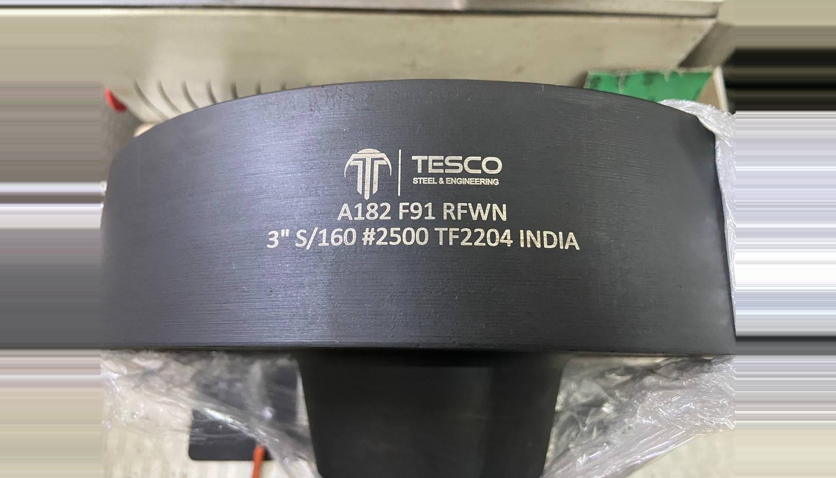
ASTM A182 F91 Weld Neck Flange (Class 2500)
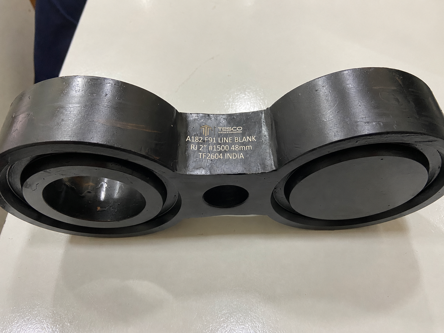
A182 F91 Line Blank / RTJ (Grade 91)
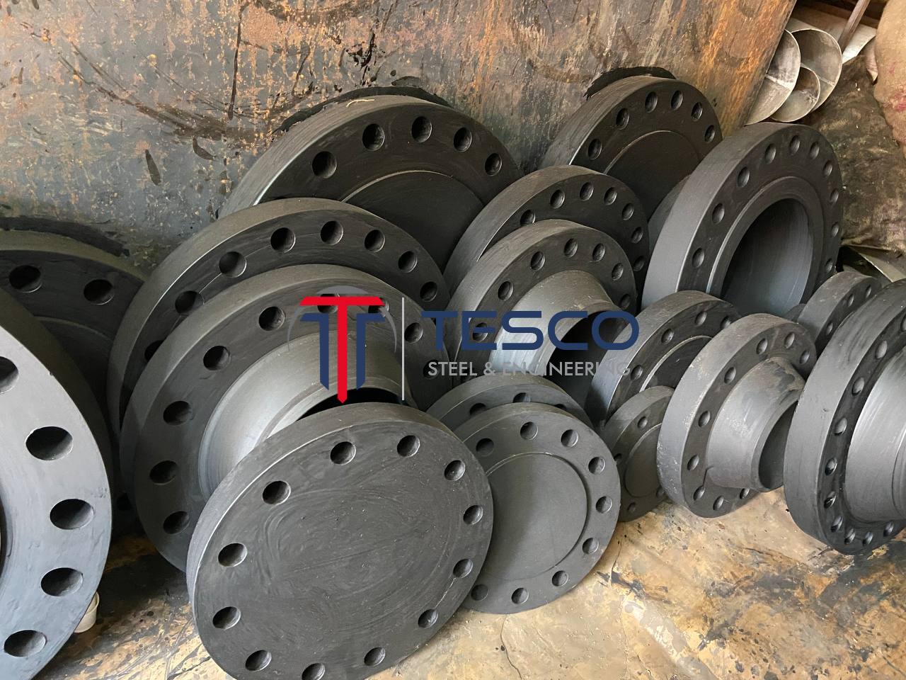
Tesco Steel & Engineering manufactures A182 F91 flanges in all types from weld neck to orifice, Class 150 to 2500 — supplied normalized-and-tempered with EN 10204 3.1 / 3.2 certification, hardness results and third-party inspection on request. Explore the wider alloy steel flange range, the classic A182 F9 flanges, the common A182 F22 flanges and A182 F5 flanges, and the flange dimension charts.
| ASTM A182 F91 flanges are available in the following specifications: | |
|---|---|
| Material Grade | ASTM A182 / A182M Grade F91 (9Cr-1Mo-V, Grade 91, creep-strength-enhanced) |
| Alloy Type | Vanadium-modified chromium-molybdenum (chrome-moly) creep-strength-enhanced steel |
| Heat Condition | Normalized and tempered (within Grade 91 limits) |
| Size | 1/2″ NB to 24″ NB (DN 15 to DN 600); larger to ASME B16.47 |
| Class / Rating | 150#, 300#, 600#, 900#, 1500#, 2500# · 3000#, 6000#, 9000# (socket-weld / threaded) |
| Pressure Ratings | PN 6 – PN 400 (PN6, 10, 16, 25, 40, 64, 100, 160, 250, 320, 400) |
| Related Specs | Pipe ASTM A335 P91; casting ASTM A217 C12A; fittings ASTM A234 WP91; plate A387 Gr91; EN X10CrMoVNb9-1 (1.4903) |
| Dimensional Standards | ASME B16.5, ASME B16.47 (Series A & B), MSS SP-44, DIN EN 1092-1 |
| Flange Types | Weld Neck (WNRF), Slip-On (SORF), Blind, Socket Weld (SWRF), Lap Joint, Threaded / Screwed, Spectacle Blind, Long Weld Neck, Orifice, Plate |
| Flange Faces | Raised Face (RF), Flat Face (FF), Ring Type Joint (RTJ), Tongue & Groove (T&G) |
| Weld Filler | E9015-B9 / ER90S-B9 (matching 9Cr-1Mo-V), preheat & mandatory PWHT |
| Testing | Hardness, hydrostatic, UT, MT/PT per spec; EN 10204 3.1 / 3.2 |
F91 is the vanadium-modified 9Cr-1Mo-V (Grade 91) chrome-moly. The vanadium, niobium and controlled nitrogen form fine carbonitride precipitates that, in a tempered-martensite matrix, give the highest creep-rupture strength of the chrome-moly grades.
| Element | ASTM A182 F91 |
|---|---|
| Carbon (C) | 0.08 – 0.12% |
| Manganese (Mn) | 0.30 – 0.60% |
| Silicon (Si) | 0.20 – 0.50% |
| Chromium (Cr) | 8.0 – 9.5% |
| Molybdenum (Mo) | 0.85 – 1.05% |
| Vanadium (V) | 0.18 – 0.25% |
| Niobium (Nb) | 0.06 – 0.10% |
| Nitrogen (N) | 0.030 – 0.070% |
| Nickel (Ni) | 0.40% max |
| Mechanical Property | ASTM A182 F91 |
|---|---|
| Tensile Strength (min) | 85 ksi (585 MPa) |
| Yield Strength (min) | 60 ksi (415 MPa) |
| Elongation (min) | ~20% |
| Hardness | ~190 – 250 HBW |
| Creep-Rupture Strength | Highest of the chrome-moly grades |
| Service Temperature | Sustained high temperature, ~600–650°C |
| Product Form | 9Cr-1Mo-V (Grade 91) Designation |
|---|---|
| Forgings / Flanges | ASTM A182 F91 |
| Seamless Pipe / Tube | ASTM A335 P91 / A213 T91 |
| Castings | ASTM A217 C12A |
| Fittings | ASTM A234 WP91 |
| Plate | ASTM A387 Gr 91 |
| European grade | X10CrMoVNb9-1 (W.Nr. 1.4903) |
F91 Weld Neck Flange (WNRF)
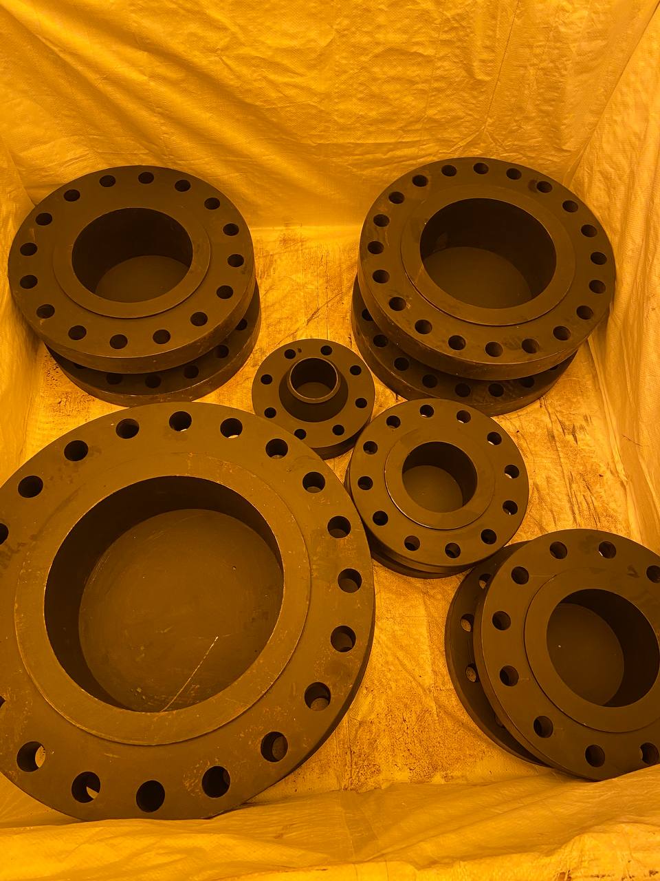
F91 Slip-On Flange (SORF)
F91 Blind Flange
| Flange Type | Description & F91-Specific Use |
|---|---|
| Weld Neck (WNRF) | Tapered hub butt-welded to pipe for high-integrity supercritical power and high-temperature piping; weld with E9015-B9 filler, controlled preheat & mandatory PWHT. |
| Slip-On (SORF) | Fillet-welded over the pipe; used in Grade 91 piping at moderate pressure. |
| Blind | Seals pipe ends and vessel nozzles in high-temperature steam and process systems. |
| Socket Weld (SWRF) | Small-bore (1/2″–2″) instrument and branch connections in hot service. |
| Lap Joint (LJRF) | Used with an F91 stub end where frequent dismantling is required. |
| Threaded (TRFF) | Internal NPT/BSP threads for non-welded connections. |
| Spectacle Blind / Long Weld Neck | Isolation spades and nozzle/long-neck flanges in A182 F91 for supercritical high-temperature duty. |
| Property | F91 | F9 | F22 | F5 |
|---|---|---|---|---|
| Nominal type | 9Cr-1Mo-V | 9Cr-1Mo | 2.25Cr-1Mo | 5Cr-0.5Mo |
| Micro-alloying | V + Nb + N | None | None | None |
| Creep-rupture strength | Highest | High | High | High |
| Yield (min) | 60 ksi | 55 ksi | 45 ksi | 40 ksi |
| Heat-treatment / weld control | Strictest (N&T + PWHT) | Tight | Standard chrome-moly | Standard chrome-moly |
| Typical role | Supercritical power, thin-wall HT | Hottest standard chrome-moly | Hydroprocessing workhorse | Hot refinery sulphur |
V/Nb/N carbonitrides give the best high-temperature creep strength of the chrome-moly family.
Higher allowable stress lets designers use thinner walls than F9/F22 at the same conditions, cutting weight.
The benchmark material for supercritical and ultra-supercritical boiler headers and steam lines.
Backed by matching pipe (A335 P91), tube (T91), castings (A217 C12A), fittings (A234 WP91) and plate (A387 Gr91).
| Industry | Typical Application |
|---|---|
| Supercritical Power Plants | Boiler headers, main steam and hot-reheat piping flanges |
| Combined-Cycle & Cogeneration | High-temperature steam-cycle flanged connections |
| Waste-to-Energy | High-temperature superheater and header flanges |
| Oil Refining | Demanding high-temperature process and heater flanges |
| Petrochemical | High-temperature, creep-critical process flanges |
| Heaters & Furnaces | Fired-heater and transfer-line flanged connections |
Made from certified 9Cr-1Mo-V with PMI verification of Cr, Mo, V and Nb — full chemistry and heat-treatment on the MTC.
Normalized and tempered within Grade 91 limits, with hardness verified for creep strength and weldability.
WNRF, SORF, blind, socket-weld, threaded, lap-joint, spectacle, LWN, orifice and plate — in RF, FF, RTJ and T&G.
EN 10204 3.1 / 3.2 MTC with hardness results, heat/lot traceability, hydrostatic and third-party inspection on request.
A182 F91 flange prices reflect the micro-alloyed 9Cr-1Mo-V content plus forging and the controlled normalizing-and-tempering — it is the premium creep-strength-enhanced chrome-moly grade for supercritical power and high-temperature service. Tesco Steel & Engineering offers competitive ex-works pricing from Mumbai with full export documentation and material traceability. Click Ask for Quote or message us on WhatsApp at +91 92233 66922 with flange type, size (NB), pressure class, quantity and documentation requirements.
Q1. What is an ASTM A182 F91 flange?
An ASTM A182 F91 flange is a forged vanadium-modified 9Cr-1Mo-V (Grade 91) chrome-moly alloy steel flange with about 9% chromium, 1% molybdenum and deliberate vanadium, niobium and nitrogen. These micro-alloying additions form fine carbonitrides that give F91 the highest creep-rupture strength of the chrome-moly family, allowing thinner, lighter high-temperature components. It is the standard for supercritical power-plant and demanding refinery high-temperature service. Flanges are made to ASTM A182 and machined to ASME B16.5 / B16.47 dimensions.
Q2. What is the chemical composition of ASTM A182 F91?
ASTM A182 F91 nominal composition: carbon 0.08–0.12%, manganese 0.30–0.60%, silicon 0.20–0.50%, chromium 8.0–9.5%, molybdenum 0.85–1.05%, vanadium 0.18–0.25%, niobium 0.06–0.10%, nitrogen 0.030–0.070%, nickel 0.40% max, aluminium 0.04% max. The vanadium, niobium and nitrogen additions to the 9Cr-1Mo base are what define the creep-strength-enhanced Grade 91.
Q3. What is the difference between A182 F9 and F91?
Both are 9% chromium chrome-moly steels. F9 is the classic 9Cr-1Mo grade. F91 (9Cr-1Mo-V, Grade 91) adds vanadium, niobium and controlled nitrogen, which form fine carbonitride precipitates that dramatically increase creep-rupture strength. F91 therefore allows thinner walls and higher temperatures than F9 and is the modern choice for supercritical power and high-temperature refinery service, but it demands tighter heat-treatment and welding control.
Q4. Why does F91 have controlled heat treatment and PWHT?
Grade 91 develops its creep strength from a tempered-martensite microstructure with fine V/Nb carbonitrides, so it must be normalized (around 1040–1080 degrees C) and tempered (around 750–780 degrees C) within tight limits, and welding requires preheat, controlled interpass temperature and mandatory post-weld heat treatment. Incorrect heat treatment or missed PWHT can leave hard, brittle zones or cause Type IV creep cracking in service, so procedure control is critical.
Q5. What are the mechanical properties of A182 F91?
Typical ASTM A182 F91 properties: tensile strength 85 ksi (585 MPa) minimum, yield strength 60 ksi (415 MPa) minimum, elongation about 20% minimum, hardness typically 190–250 HBW. It has the highest creep-rupture strength of the chrome-moly grades, supplied in the normalized-and-tempered condition.
Q6. What temperature can A182 F91 flanges handle?
A182 F91 is used for sustained high-temperature service up to about 600–650 degrees C with exceptional creep strength, which is why it is the standard for supercritical and ultra-supercritical boiler, header and steam-line components. Its high creep strength allows thinner sections than lower-alloy chrome-moly grades at the same conditions.
Q7. What standards apply to A182 F91 flanges?
A182 F91 flanges are forged to ASTM A182/A182M (Grade F91) and machined to ASME B16.5 (1/2 inch to 24 inch) or ASME B16.47 / MSS SP-44 for larger sizes, with EN 1092-1 for PN-rated flanges. Material is supplied normalized-and-tempered with EN 10204 3.1 / 3.2 certification. Matching pipe is ASTM A335 P91, casting ASTM A217 C12A, fittings ASTM A234 WP91; the European grade is X10CrMoVNb9-1 (1.4903).
Q8. Can A182 F91 flanges be welded?
Yes, with strict procedure control. F91 is welded with matching 9Cr-1Mo-V consumables (e.g. E9015-B9 / ER90S-B9), with preheat (typically 200–300 degrees C), tightly controlled interpass temperature, and mandatory post-weld heat treatment (temper around 750–770 degrees C). Heat-treatment and welding parameters must be closely controlled to develop creep strength and avoid Type IV cracking.
Q9. What industries use A182 F91 flanges?
ASTM A182 F91 flanges are used in supercritical and ultra-supercritical power plants (boiler headers, main steam and hot-reheat piping), high-temperature refinery and petrochemical service, and waste-to-energy and combined-cycle plant where the highest chrome-moly creep strength is required to minimise wall thickness and weight.
Q10. Are A182 F91 flanges supplied with material test certificates?
Yes. Every A182 F91 flange is supplied with EN 10204 3.1 (or 3.2) mill test certificates confirming chemistry (including V, Nb, N), mechanical properties, heat-treatment condition, hardness and heat/lot traceability, with hydrostatic testing and third-party inspection on request. Tesco Steel & Engineering is an ISO 9001:2015 certified manufacturer and exporter from Mumbai, India.