Q Syphon Manufacturer
TES-LOK Q-Syphon (Coil / Helical Syphon) — high-volume condensate barrier for HP steam, superheated steam & high-pulsation services. SS 304 · SS 316 · Brass · Inconel · Monel · NPT · BSPT · BSPP · Up to 6,000 PSI · ISO 9001:2015 certified.
ISO 9001:2015 Certified
Up to 400 °C
Up to 6,000 PSI
NPT · BSPT · BSPP
HP & Superheated Steam
SS 304 · SS 316 · Brass · Inconel · Monel
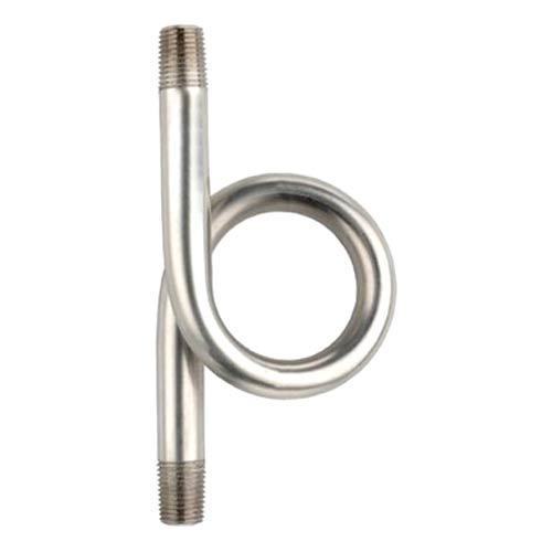
Q-Type Coil Syphon
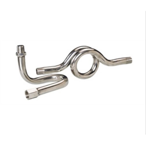
Syphon Tube Assembly
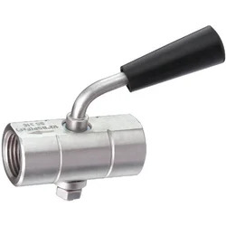
Q Syphon with Gauge Cock
Tesco Steel & Engineering manufactures TES-LOK Q-Syphon (also referred to as coil syphon or helical syphon) — the premium condensate-barrier fitting for high-pressure steam, superheated steam, and high-pulsation process services where a standard U-syphon's single-loop condensate volume is insufficient. The Q-syphon's multi-turn coil geometry stores 3–5 times more condensate than a U-type loop, providing superior thermal mass, more stable condensate level maintenance under sustained superheat, and significantly better hydraulic pulsation damping. TES-LOK Q-syphons are manufactured in SS 304, SS 316, Brass, Inconel, Monel, and Hastelloy with NPT, BSPT, and BSPP thread ends — the standard choice for power plant, refinery, and offshore HP steam instrumentation.
Why Choose a Q-Syphon Over a U-Syphon
The Coil Advantage — Volume, Mass & Damping
A Q-syphon (coil) forms multiple turns in one plane — typically 3 to 6 turns — creating a significantly larger condensate reservoir than a single U-loop. The larger water volume means: (1) more thermal mass to absorb heat from intermittent superheated steam surges without the condensate level dropping and exposing the gauge; (2) greater hydraulic capacitance that attenuates pressure spikes and eliminates pointer flutter; (3) a self-restoring condensate level — even if partial evaporation occurs, the coil retains enough liquid to maintain the barrier until the next condensation cycle restores the level.
3–5× More Condensate Volume
A Q-coil holds 20–60 mL of condensate vs 5–15 mL for a U-type. The larger reservoir maintains barrier integrity through steam pressure surges and intermittent superheat without running dry.
Superior Pulsation Damping
Multiple coil turns act as a distributed hydraulic snubber. Pressure spikes from reciprocating pumps, control valve chatter, and steam hammer are attenuated before reaching the gauge bourdon tube.
Superheated Steam Capable
Superheated steam condenses more slowly than saturated steam. The coil's larger volume compensates — even if steam reaches the upper coil turns, sufficient condensate remains in the lower turns to maintain the hydraulic seal.
Q-Syphon vs U-Syphon — Detailed Comparison
| Parameter | Q-Syphon (Coil) | U-Syphon (Pigtail) | When Q is Required |
|---|
| Coil Turns |
3–6 turns (helical or pancake) |
1 open loop |
Always when >40 bar or superheated |
| Condensate Volume |
20–60 mL (high) |
5–15 mL (moderate) |
High-pressure services where volume is safety-critical |
| Steam Pressure Range |
Any — LP, MP, HP, superheated |
Adequate to ~40 bar (MP steam) |
HP steam >40 bar; superheated steam services |
| Pulsation Damping |
Excellent — multi-turn hydraulic capacitance |
Good — single-loop moderate damping |
Reciprocating compressors, turbine exhausts, noisy steam headers |
| Thermal Mass |
High — coil absorbs more heat per cycle |
Lower — smaller water mass |
Superheated steam; steam lines with intermittent surges |
| Height / Footprint |
Compact coil diameter (60–100 mm); slightly more height than U-type |
Narrow profile (60–110 mm height); minimal footprint |
Space is not critical; use Q-type for superior performance |
| Applicable Standards |
DIN 16282, BS 6212, ASME B31.1 (power piping preference) |
DIN 16282, BS 6212 |
Power plant and ASME B31.1 services specify coil-type syphons |
| Cost vs U-type |
~20–40% higher (multi-turn coil forming) |
Lowest cost syphon |
Cost difference negligible vs gauge replacement cost at HP |
Available Thread Forms & End Connections
| Thread Standard | Designation | Seal Mechanism | Compatible Gauges |
|---|
| NPT |
ASME B1.20.1 — 60° tapered 1:16 |
Thread interference; PTFE tape or high-temp anaerobic sealant |
US, Middle East, Indian process gauges |
| BSPT |
BS 21 / ISO 7 — 55° tapered 1:16 |
Thread interference; PTFE tape or anaerobic sealant |
European, Asian, and UK gauges with tapered port |
| BSPP (BSP) |
BS 2779 / ISO 228 — 55° parallel |
Dowty bonded seal in gauge boss socket |
European parallel-socket gauges; Swagelok accessories |
| SAE 45° Flare |
SAE J512 |
Metal-to-metal 45° flare seat |
Hydraulic instruments, mobile plant gauges |
BSPP Thread Warning — No PTFE Tape on Parallel Threads:
BSPP (parallel BSP) Q-syphon threads seal on the face of the gauge boss socket, not on the thread taper. Never apply PTFE tape to BSPP threads. Fit a Dowty bonded seal (metal-backed rubber washer, EN ISO 1179-1) into the gauge boss socket before threading on the syphon. PTFE tape on a parallel thread creates a false torque signal — the joint will appear tight but will weep under HP steam pressure cycling. NPT and BSPT (both tapered) require 2–3 wraps of PTFE tape clockwise from the second thread.
Thread Sealant Selection
| Thread Type | Sealant Method | Application Notes |
|---|
| NPT (Tapered) |
PTFE tape — 2–3 wraps clockwise from 2nd thread; or high-temp anaerobic sealant rated to steam temperature |
Leave first thread bare; 1½–2 turns past handtight on assembly; do not over-tighten on HP connections |
| BSPT (Tapered) |
PTFE tape — 2–3 wraps; or rated anaerobic sealant |
Do not cross-thread NPT into BSPT boss — 60° vs 55° flank angle will cause cross-threading and possible gauge boss damage at HP |
| BSPP (Parallel) |
Dowty bonded seal (EN ISO 1179-1) seated in gauge socket — no PTFE tape |
Inspect Dowty seal face for scoring; always renew Dowty seal on each disassembly at HP service |
Standard Size Range
| Connection Size | Tube OD (Body) | Coil OD (Approx.) | Coil Turns | NPT | BSPT | BSPP | Max Pressure (SS) |
|---|
| 1/4" | 10–12 mm | 55–65 mm | 3–4 | ✓ | ✓ | ✓ | 6,000 PSI |
| 3/8" | 14–16 mm | 65–80 mm | 3–5 | ✓ | ✓ | ✓ | 4,500 PSI |
| 1/2" | 18–22 mm | 80–100 mm | 3–6 | ✓ | ✓ | ✓ | 3,500 PSI |
| 3/4" | 24–28 mm | 95–120 mm | 3–5 | ✓ | ✓ | — | 2,500 PSI |
| Custom coil OD / turns | Per drawing | Per drawing | Per spec | ✓ | ✓ | ✓ | Per calculation |
Material & Technical Specifications
| Parameter | Details |
|---|
| Brand | TES-LOK (Tesco Steel & Engineering) |
| Product Type | Q-Syphon — Multi-turn Coil / Helical / Pancake configuration |
| Connection Size | 1/4" to 3/4" NPT / BSPT / BSPP; larger sizes on request |
| Material — SS | SS 304 (ASTM A276/A479), SS 316 (ASTM A276/A479), SS 316L |
| Material — Brass | ASTM B283 — C36000 free-machining brass (low-pressure steam only) |
| Material — High Alloy | Inconel 600/625 (ASTM B166), Monel 400 (ASTM B164), Hastelloy C-276 (ASTM B574) |
| PTFE Ferrule Standard | ASTM D1710 / ASTM D3294 |
| Pressure Rating — SS | Up to 6,000 PSI (413 bar) at ambient; de-rated per ASME B31.3 at elevated temperature |
| Pressure Rating — Brass | 300 PSI / 1,000 PSI (low-pressure applications only) |
| Working Temperature | –50 °C to +400 °C (material dependent) |
| Coil Turns | 3–6 turns standard; custom coil count on request |
| Condensate Volume | 20–60 mL (depending on coil OD and turns) |
| Surface Finish | Bright annealed / electropolished / pickled & passivated per ASTM A380 |
| Design Standards | DIN 16282 (syphon tubes), BS 6212 (gauge fittings), ASME B16.14 (threaded accessories), ASME B31.1 (power piping applications) |
| Quality Standard | ISO 9001:2015 certified manufacturing |
| Certifications Available | EN 10204 3.1 MTR, PMI, NACE MR0175, Hydrostatic test certificate |
| Interchangeability | Fully compatible with Swagelok, Parker A-LOK, Ham-Let, Hoke gauge accessories |
Material Selection Guide
| Steam Service | Pressure / Temperature | Recommended Material | Reason |
|---|
| LP saturated steam |
Up to 12 bar / 190 °C |
Brass or SS 304 |
Brass adequate for LP heating steam; SS 304 preferred for longevity |
| MP saturated steam |
12–40 bar / 190–250 °C |
SS 316 |
Brass unsuitable above 12 bar; SS 316 handles MP steam reliably |
| HP saturated / superheated steam |
>40 bar / >250 °C |
SS 316 or SS 316L |
ASME B31.1 power piping; SS 316L preferred for weld-connected flanged versions |
| Seawater-contaminated or marine steam |
Any pressure |
Monel 400 |
Chloride SCC immunity; resistant to steam condensate in salt-laden atmospheres |
| Acid gas or sour steam |
Any pressure |
Hastelloy C-276 |
Broad acid / H₂S resistance; NACE MR0175 compliant for sour service |
| Caustic or ammonia steam |
Up to 250 °C |
Inconel 600 or SS 316L |
Inconel 600 preferred for high-caustic concentrations; SS 316L for moderate caustic |
Installation Procedure
Orientation Rule for Q-Syphon Coils: The Q-syphon coil must be installed in a vertical plane with the process connection at the bottom and the gauge connection at the top. The coil loops must hang below the gauge port so gravity holds the condensate in the coil. Never mount the coil horizontally — condensate will drain out of the open lower half of the coil and the barrier will fail.
1
Verify thread form before assembly: Confirm the Q-syphon's thread standard (NPT / BSPT / BSPP) matches both the process boss and the gauge bottom connection. NPT (60° flank) and BSPT (55° flank) are not interchangeable — mixing damages both fittings. Check gauge data plate or supplier specification.
2
Apply sealant to process-side thread: NPT / BSPT: apply 2–3 wraps of PTFE tape clockwise from the second thread. BSPP: place a Dowty bonded seal in the process boss socket. Leave the gauge-side port open for pre-filling in the next step.
3
Mount coil on process connection: Thread the lower leg of the Q-syphon into the process boss or root valve. Tighten 1½–2 turns past handtight (NPT / BSPT) or to Dowty torque specification for BSPP (typically 20–40 N·m for 1/2"). Orient coil vertically — coil plane vertical, process port at bottom, gauge port at top.
4
Pre-fill the coil with water — mandatory: Using a filling syringe or bottle, fill all coil turns completely with clean water through the upper (gauge-side) port. For a Q-syphon this may require 30–60 mL of water. Continue filling until water overflows at the top — all turns must be filled. An empty or partially filled coil provides no protection.
5
Fit the pressure gauge: Apply sealant to the gauge-side thread and connect the pressure gauge immediately — do not allow the pre-fill water to drain before connecting the gauge. Tighten to gauge manufacturer's torque specification.
6
Open isolation valve gradually: Crack the root valve or gauge cock very slowly over 15–20 seconds. HP steam admission must be controlled — sudden opening can cause condensate hammer in the coil, spiking gauge pressure to damaging levels. Wait 3–5 minutes for condensate level to stabilise before reading.
7
Leak check under pressure: Inspect all threaded joints with steam-rated leak detection solution. For HP connections, snug by ¼ turn maximum while live. Never re-tape a live HP joint — isolate, depressurise, cool fully, disassemble, re-seal, and re-pressurise.
8
Periodic inspection: During plant turnarounds, verify the coil has no visible corrosion, thread wear, or mechanical damage. Perform a water fill test — fill coil through gauge port and confirm it holds water without leaking through threads or body. Replace if the coil cannot hold water or if wall thinning is detected.
HP Steam — Never Open Without Pre-Fill:
On high-pressure steam lines, operating a pressure gauge without a completely pre-filled Q-syphon will destroy the gauge bourdon tube within seconds of steam admission. At >40 bar, steam temperature exceeds 250 °C — direct contact with the gauge element at this temperature causes immediate thermal failure. At power plant pressures (>100 bar), bourdon tube rupture under these conditions can result in scalding injury. Pre-fill is mandatory before any valve operation.
Why Choose TES-LOK Q-Syphons
Multi-Turn Coil — More Condensate
3–6 coil turns provide 20–60 mL condensate reservoir — 3 to 5 times the volume of a U-type. Maintains protective condensate level even under sustained superheated steam exposure.
6,000 PSI Rated
Precision-machined SS 316 construction rated to 6,000 PSI (413 bar) at ambient, covering all HP steam applications from industrial boilers to power plant steam turbine inlet gauges.
Best-in-Class Pulsation Damping
Multi-turn hydraulic capacitance eliminates gauge pointer flutter and hunting caused by steam header pressure oscillations, reciprocating pump surges, and control valve seat flow instability.
Full Alloy Range
SS 304, SS 316, Brass, Inconel 600/625, Monel 400, Hastelloy C-276 — covering clean steam, sour service, chloride-bearing condensate, caustic steam, and pharmaceutical clean steam.
Certified & Traceable
ISO 9001:2015 certified manufacturing. EN 10204 3.1 MTR, PMI, and hydrostatic test certificates on request — meeting EPC, FEED, and owner-inspector documentation requirements for HP steam projects.
Stock & Fast Delivery
1/4" and 1/2" Q-syphons in SS 316 maintained in Mumbai warehouse. Urgent dispatch for plant shutdowns and HP steam gauge changeouts. Bulk supply for power plant outage kits available.
Applications
| Industry / Facility | Specific Application | Recommended Material |
|---|
| Power Generation | HP/LP steam drum pressure gauges, turbine inlet steam gauges, boiler feed pump discharge instruments, superheater outlet gauges | SS 316 (ASME B31.1) |
| Oil & Gas Refineries | HP process steam headers, reboiler steam instruments, steam injection well gauges, sour service steam measurement | SS 316 / Hastelloy C-276 (sour) |
| Petrochemical Plants | HP steam cracker instruments, steam reformer header gauges, steam turbine-driven compressor governor instruments | SS 316L |
| Offshore Platforms | HP steam utility gauges, gas turbine waste heat recovery steam instruments, marine boiler pressure measurement | Monel 400 (chloride) |
| Steel & Metals | Blast furnace steam injection pressure gauges, continuous caster steam cooling instruments | SS 316 |
| Pharmaceutical | HP autoclave steam gauges, steriliser steam pressure instruments (SIP at 134 °C / 3 bar) | SS 316L electropolished |
| Pulp & Paper | Digester steam pressure gauges, evaporator steam-side instruments, paper dryer steam header gauges | SS 316 |
| Sugar & Distillery | HP evaporation steam instruments, vacuum pan steam pressure gauges, distillation column steam measurements | SS 316 / SS 304 |
Frequently Asked Questions
What does "Q-syphon" mean and why is it called that?
The "Q" designation refers to the shape of the coil — when viewed from the side, a multi-turn helical or pancake coil with a straight upper and lower connection leg resembles the letter Q. The name is widely used in the instrumentation industry to distinguish coil-type syphons from U-type (pigtail) syphons. In some catalogues the same product is called a "coil syphon," "helical syphon," or "steam coil." All refer to the same multi-turn wound tube geometry. TES-LOK manufactures both pancake (flat) coil and helical coil configurations.
When must I use a Q-syphon instead of a U-syphon?
A Q-syphon is required (or strongly recommended) in four situations: (1) HP steam above 40 bar — the larger condensate volume is needed to maintain barrier integrity against steam's higher enthalpy at elevated pressures; (2) Superheated steam service — superheated steam condenses slowly, so a larger reservoir prevents the condensate level from dropping and exposing the gauge; (3) High-pulsation services — reciprocating compressors, turbine exhaust steam, noisy headers — where the Q-coil's extra hydraulic capacitance eliminates pointer vibration; (4) Power plant / ASME B31.1 services — engineering specifications for power piping frequently mandate coil-type syphons by reference to DIN 16282 or project instrument specification sheets.
How many coil turns should I specify?
Standard TES-LOK Q-syphons are supplied with 3 turns (minimum for adequate condensate volume) up to 6 turns for high-pressure or superheated steam with severe pulsation. For general HP saturated steam up to 100 bar, 3–4 turns are typically sufficient. For superheated steam above 300 °C, or for services with pronounced pressure pulsations, 5–6 turns provide greater thermal mass and hydraulic damping. Custom coil counts are available — specify steam conditions, line pressure, and whether a snubber is separately installed when requesting a quote.
Can a Q-syphon be installed in any orientation?
No. A Q-syphon must always be installed in a vertical plane with the process connection at the bottom and the gauge connection at the top. The coil loops must hang downward below the gauge port so gravity keeps the condensate in the lower turns. The process connection can be at any clock angle relative to the gauge connection as long as the coil sits below both connection ports. Horizontal installation causes the lower half of the coil to drain, losing the condensate barrier. If a horizontal gauge installation is unavoidable, use a separate condensate pot mounted below the gauge with tube connections to both.
Do I need to pre-fill a Q-syphon every time I reinstall a gauge?
Yes — every time the syphon is opened to atmosphere (gauge removed, syphon removed for maintenance, or isolation valve opened with the gauge disconnected), the coil must be completely re-filled before reconnecting and reopening the steam valve. Once commissioned in a closed system that remains pressurised, the syphon does not need re-filling because the condensate is trapped by the process pressure above and gravity below. Whenever the system is depressurised and opened, assume the coil has drained partially and re-fill as a standard precaution before restart.
What is the difference between a pancake coil syphon and a helical coil syphon?
Both are Q-type (coil) syphons differing only in how the coil is wound. A pancake coil (flat coil) has all turns wound in a single horizontal plane — the result is a flat disc-shaped coil with a small vertical height but larger outside diameter. A helical coil has turns stacked vertically like a spring — the result is a taller but narrower-diameter coil. Both hold similar condensate volumes for the same tube diameter and number of turns. The choice is driven by the physical space available at the gauge location. Pancake coils are preferred where vertical height above the gauge connection boss is restricted; helical coils where lateral space is limited.
Should I specify SS 316 or SS 316L for a Q-syphon on HP steam service?
For threaded Q-syphons (NPT / BSPT / BSPP), SS 316 (standard grade) is adequate for all HP steam applications up to 400 °C — the low-carbon "L" grade is not required because there is no welding on a threaded syphon that would risk sensitisation and intergranular corrosion. Specify SS 316L when: (1) the Q-syphon will be welded to a pipe stub or flanged into a welded assembly; (2) the project specification mandates SS 316L for all pressure-retaining items; or (3) the process fluid may contain chlorides above 60 °C (where the lower carbon content slightly reduces sensitisation risk). If in doubt, SS 316L has no disadvantage over SS 316 for threaded syphon service — specify it for consistency.
Are TES-LOK Q-syphons compatible with Swagelok or Parker gauge accessories?
Yes. TES-LOK Q-syphons are manufactured to ASME B1.20.1 (NPT), BS 21/ISO 7 (BSPT), and BS 2779/ISO 228 (BSPP) thread standards — dimensionally identical to Swagelok, Parker A-LOK, Ham-Let, and Hoke gauge accessories. Thread pitch, taper, and flank angles match exactly; no adaptors or converters are required. Specify the correct thread standard when ordering to match your existing gauge and root valve inventory.

