

Tesco Steel & Engineering manufactures expander flanges — weld-neck-style flanges that increase (expand) the pipe bore up to a larger flange size in a single fitting, combining a concentric reducer and a flange in one. Welded to the smaller pipe, the tapered hub opens out to a larger flanged face, so a line can step up to bigger equipment, a meter run, or a pump nozzle without a separate reducer plus flange. Made to ANSI/ASME B16.5 in Class 150, 300 and 400. A105, SS 304, 316, 321, Monel, Inconel, and Incoloy. PN6 to PN400. ISO 9001:2015 certified. Made in India.
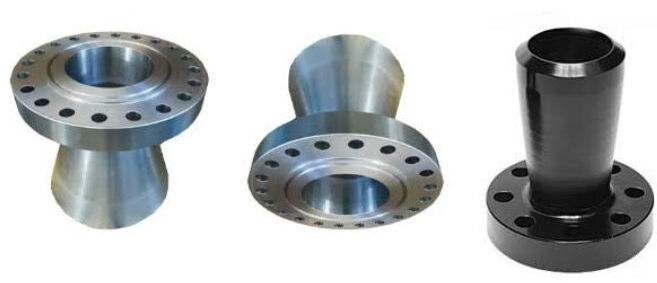
Expander Flange
Expander flanges (and their counterpart reducing flanges) save space, weight, and a weld at size transitions. Tesco Steel & Engineering supplies them to ANSI B16.5 in the full material range — dimensioned per the tables below and compatible with our standard weld neck flanges; see the flange dimensions charts.
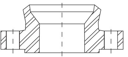
Expander Flange Dimensions (A, B, C, D, D2, H, J, K, CT)
| Criterion | Expander Flange | Reducer + Separate Flange |
|---|---|---|
| Components | Single fitting | Concentric reducer + weld-neck flange |
| Welds | One (to the run pipe) | Two or more |
| Length & weight | Shorter & lighter | Longer & heavier |
| Leak paths | Fewer welds, fewer leaks | More welds, more inspection |
| Best for | Pump/compressor nozzles, meter runs, tight layouts | General size changes where space allows |
The expander flange replaces a reducer and a flange with one shorter, lighter fitting and a single weld — ideal where space at a pump, compressor, or flow-meter is tight. A reducing flange does the opposite (steps a larger bore down to a smaller flange) where flow conditions allow.
| Pipe Size
(NPS) |
Outside
Diameter of Flange A |
Diameter
of Raised Face B |
Thickness
of Flange C |
Diameter
of Bore D |
Diameter
of Bore D2 |
Diameter
of Hub at Weld H |
Diameter
of Hub at Base J |
Length
of Hub K |
Compound
Taper CT |
Slope
at Bevel SB |
Number
of Bolt Holes |
Diameter
of Bolt Holes |
Bolt
Circle Diameter P |
Approx.
Weight (lb) |
Design
Type |
|---|---|---|---|---|---|---|---|---|---|---|---|---|---|---|---|
| 2 x 3 | 6 | 3 5/8 | 3/4 | 2.067 | 3.068 | 3.500 | 3 1/16 | 2 1/2 | – | 16° | 4 | 3/4 | 4 3/4 | 6 | A |
| 2 x 4 | 6 | 3 5/8 | 3/4 | 2.067 | 4.026 | 4.500 | 3 1/16 | 3 5/8 | 1/2 | 29° * | 4 | 3/4 | 4 3/4 | 6 | C |
| 3 x 4 | 7 1/2 | 5 | 15/16 | 3.068 | 4.026 | 4.500 | 4 1/4 | 2 3/4 | – | 15° | 4 | 3/4 | 6 | 11 | A |
| 4 x 6 | 9 | 6 3/16 | 15/16 | 4.026 | 6.065 | 6.625 | 5 5/16 | 3 1/4 | 1/2 | 30° * | 8 | 3/4 | 7 1/2 | 15 | C |
| 6 x 8 | 11 | 8 1/2 | 1 | 6.065 | 7.981 | 8.625 | 7 9/16 | 4 | 1/2 | 28° * | 8 | 7/8 | 9 1/2 | 24 | C |
| 8 x 10 | 13 1/2 | 10 5/8 | 1 1/8 | 7.981 | 10.020 | 10.750 | 9 11/16 | 4 | 1/2 | 29° * | 8 | 7/8 | 11 3/4 | 39 | C |
| 8 x 12 | 13 1/2 | 10 5/8 | 1 1/8 | 7.981 | 12.000 | 12.750 | 9 11/16 | 6 | 1/2 | 29° * | 8 | 7/8 | 11 3/4 | 39 | C |
| 10 x 12 | 16 | 12 3/4 | 1 3/16 | 10.020 | 12.000 | 12.750 | 12 | 3 15/16 | 1/2 | 39° * | 12 | 1 | 14 1/4 | 52 | C |
| 10 x 14 | 16 | 12 3/4 | 1 3/16 | 10.020 | 13.250 | 14.000 | 12 | 5 7/16 | 5/8 | 30° * | 12 | 1 | 14 1/4 | 52 | C |
| 12 x 14 | 19 | 15 | 1 1/4 | 12.000 | 13.250 | 14.000 | 14 3/8 | 4 1/2 | – | 11° | 12 | 1 | 17 | 80 | D |
| 12 x 16 | 19 | 15 | 1 1/4 | 12.000 | 15.250 | 16.000 | 14 3/8 | 4 13/16 | 5/8 | 30° * | 12 | 1 | 17 | 80 | C |
| 14 x 16 | 21 | 16 1/4 | 1 3/8 | 13.250 | 15.250 | 16.000 | 15 3/4 | 5 | – | 15° | 12 | 1 1/8 | 18 3/4 | 120 | A |
| 14 x 18 | 21 | 16 1/4 | 1 3/8 | 13.250 | 17.250 | 18.000 | 15 3/4 | 5 11/16 | 5/8 | 30° * | 12 | 1 1/8 | 18 3/4 | 120 | C |
| 18 x 20 | 25 | 21 | 1 9/16 | 17.250 | 19.250 | 20.000 | 19 7/8 | 5 1/2 | – | 14° | 16 | 1 1/4 | 22 3/4 | 140 | A |
| 18 x 24 | 25 | 21 | 1 9/16 | 17.250 | 23.250 | 24.000 | 19 7/8 | 8 13/16 | 5/8 | 28° * | 16 | 1 1/4 | 22 3/4 | 140 | C |
| 20 x 24 | 27 1/2 | 23 | 1 11/16 | 19.250 | 23.250 | 24.000 | 22 | 6 7/16 | 5/8 | 30° * | 20 | 1 1/4 | 25 | 170 | C |
| 24 x 30 | 32 | 27 1/4 | 1 7/8 | 23.250 | 29.250 | 30.000 | 26 1/8 | 8 11/16 | 3/4 | 30° * | 20 | 1 3/8 | 29 1/2 | 260 | C |
| Pipe Size
(NPS) |
Outside
Diameter of Flange A |
Diameter
of Raised Face B |
Thickness
of Flange C |
Diameter
of Bore D |
Diameter
of Bore D2 |
Diameter
of Hub at Weld H |
Diameter
of Hub at Base J |
Length
of Hub K |
Compound
Taper CT |
Slope
at Bevel SB |
Number
of Bolt Holes |
Diameter
of Bolt Holes |
Bolt
Circle Diameter P |
Approx.
Weight (lb) |
Design
Type |
|---|---|---|---|---|---|---|---|---|---|---|---|---|---|---|---|
| 2 x 3 | 6 1/2 | 3 5/8 | 7/8 | 2.067 | 3.068 | 2.375 | 3 5/16 | 2 3/4 | – | 15° | 8 | 3/4 | 5 | 9 | A |
| 2 x 4 | 6 1/2 | 3 5/8 | 7/8 | 2.067 | 4.026 | 2.375 | 3 5/16 | 2 3/4 | 1/2 | 29° * | 8 | 3/4 | 5 | 9 | C |
| 3 x 4 | 8 1/4 | 5 | 1 1/8 | 3.068 | 4.026 | 3.500 | 4 5/8 | 3 1/8 | – | 13° | 8 | 7/8 | 6 5/8 | 15 | D |
| 4 x 6 | 10 | 6 3/16 | 1 1/4 | 4.026 | 6.065 | 4.500 | 5 3/4 | 3 3/8 | 1/2 | 30° * | 8 | 7/8 | 7 7/8 | 25 | C |
| 6 x 8 | 12 1/2 | 8 1/2 | 1 7/16 | 6.065 | 7.981 | 6.625 | 8 1/8 | 3 7/8 | 1/2 | 22° * | 12 | 7/8 | 10 5/8 | 42 | B |
| 8 x 10 | 15 | 10 5/8 | 1 5/8 | 7.981 | 10.020 | 8.625 | 10 1/4 | 4 3/8 | – | 20° | 12 | 1 | 13 | 67 | A |
| 10 x 12 | 17 1/2 | 12 3/4 | 1 7/8 | 10.020 | 12.000 | 10.750 | 12 5/8 | 4 5/8 | – | 20° | 16 | 1 1/8 | 15 1/4 | 91 | A |
| 12 x 14 | 20 1/2 | 15 | 2 | 12.000 | 13.250 | 12.750 | 14 3/4 | 5 1/8 | – | 11° | 16 | 1 1/4 | 17 3/4 | 138 | D |
| 14 x 16 | 23 | 16 1/4 | 2 1/8 | 13.250 | 15.250 | 14.000 | 16 3/4 | 5 5/8 | – | 16° | 20 | 1 1/4 | 20 1/4 | 186 | D |
| 16 x 18 | 25 1/2 | 18 1/2 | 2 1/4 | 15.250 | 17.250 | 16.000 | 19 | 5 3/4 | – | 16° | 20 | 1 3/8 | 22 1/2 | 246 | D |
| 18 x 20 | 28 | 21 | 2 3/8 | 17.250 | 19.250 | 18.000 | 21 | 6 1/4 | – | 14° | 24 | 1 3/8 | 24 3/4 | 305 | D |
| 20 x 24 | 30 1/2 | 23 | 2 1/2 | 19.250 | 23.250 | 20.000 | 23 1/8 | 6 3/8 | 5/8 | 29° * | 24 | 1 3/8 | 27 | 378 | B |
| 24 x 30 | 36 | 27 1/4 | 2 3/4 | 23.250 | 29.250 | 24.000 | 27 5/8 | 6 5/8 | 3/4 | 30° * | 24 | 1 5/8 | 32 | 545 | B |
| Pipe Size
(NPS) |
Outside
Diameter of Flange A |
Diameter
of Raised Face B |
Thickness
of Flange C |
Diameter
of Bore D |
Diameter
of Bore D2 |
Diameter
of Hub at Weld H |
Diameter
of Hub at Base J |
Length
of Hub K |
Compound
Taper CT |
Slope
at Bevel SB |
Number
of Bolt Holes |
Diameter
of Bolt Holes |
Bolt
Circle Diameter P |
Approx.
Weight (lb) |
Design
Type |
|---|---|---|---|---|---|---|---|---|---|---|---|---|---|---|---|
| 2 x 3 | 6 1/2 | 3 5/8 | 1 | * | * | 2.375 | 3 5/16 | 2 7/8 | – | 14° | 8 | 3/4 | 5 | 12 | A |
| 2 x 4 | 6 1/2 | 3 5/8 | 1 | * | * | 2.375 | 3 5/16 | 2 7/8 | 1/2 | 29° ** | 8 | 3/4 | 5 | 12 | C |
| 3 x 4 | 8 1/4 | 5 | 1 1/4 | * | * | 3.500 | 4 5/8 | 3 1/4 | – | 13° | 8 | 7/8 | 6 5/8 | 23 | D |
| 4 x 6 | 10 3/4 | 6 3/16 | 1 1/2 | * | * | 4.500 | 6 | 4 | – | 21° | 8 | 1 | 8 1/2 | 42 | A |
| 6 x 8 | 14 | 8 1/2 | 1 7/8 | * | * | 6.625 | 8 3/4 | 4 5/8 | – | 21° | 12 | 1 1/8 | 11 1/2 | 81 | D |
| 8 x 10 | 16 1/2 | 10 5/8 | 2 3/16 | * | * | 8.625 | 10 3/4 | 5 1/4 | – | 19° | 12 | 1 1/4 | 13 3/4 | 117 | D |
| 10 x 12 | 20 | 12 3/4 | 2 1/2 | * | * | 10.750 | 13 1/2 | 6 | – | 16° | 16 | 1 3/8 | 17 | 189 | D |
| 12 x 14 | 22 | 15 | 2 5/8 | * | * | 12.750 | 15 3/4 | 6 1/8 | – | 10° | 20 | 1 3/8 | 19 1/4 | 226 | D |
| 14 x 16 | 23 3/4 | 16 1/4 | 2 3/4 | * | * | 14.000 | 17 | 6 1/2 | – | 15° | 20 | 1 1/2 | 20 3/4 | 347 | D |
| 16 x 18 | 27 | 18 1/2 | 3 | * | * | 16.000 | 19 1/2 | 7 | – | 14° | 20 | 1 5/8 | 23 3/4 | 481 | D |
| 18 x 20 | 29 1/4 | 21 | 3 1/4 | * | * | 18.000 | 21 1/2 | 7 1/4 | – | 14° | 20 | 1 3/4 | 25 3/4 | 555 | D |
| 20 x 24 | 32 | 23 | 3 1/2 | * | * | 20.00 | 24 | 7 1/2 | 5/8 | 28° ** | 24 | 1 3/4 | 28 1/2 | 690 | E |
| 24 x 30 | 37 | 27 1/4 | 4 | * | * | 24.00 | 28 1/4 | 8 | 3/4 | 28° ** | 24 | 2 | 33 | 977 | C |
Combines a concentric reducer and a weld-neck flange in a single fitting, made with one weld instead of two or more.
Shorter and lighter than a reducer-plus-flange assembly — ideal at congested pump, compressor, and meter connections.
One weld means fewer joints to inspect and fewer potential leak points, improving integrity at the size transition.
The gentle internal taper limits turbulence and pressure loss, helping accuracy at flow-meter runs.
A105, SS 304/316/321, Monel, Inconel, and Incoloy for gas, steam, and corrosive or high-temperature service.
Made to ANSI/ASME B16.5 facings & ratings or to your drawing, certified with EN 10204 3.1 MTC.
| Material | Properties | Typical Use |
|---|---|---|
| A105 Carbon Steel | Strong, economical | Non-corrosive gas, steam & liquid lines |
| SS 304 / 316 / 316L | Good corrosion resistance | Process, chemical & hygienic lines |
| SS 321 | Stabilised for high temperature | High-temperature steam & gas |
| Monel 400 | Excellent in HF & marine media | HF, seawater & reducing media |
| Inconel / Incoloy | High-temperature & corrosion resistance | High-temperature & corrosive lines |
| Industry | Typical Use | Why Expander Flange |
|---|---|---|
| Oil & Gas | Pump/compressor suction & discharge | Reducer + flange in one; saves space |
| Refinery & Petrochemical | Equipment & meter-run transitions | Smooth taper; full material range |
| Power Generation | Pump & boiler nozzle connections | SS 321 high-temperature service |
| Chemical Plants | Corrosive-line size changes | Monel / Inconel / Incoloy |
| Flow Measurement | Meter-run size transitions | Low-turbulence bore expansion |
| Pipelines | Diameter step-ups | Shorter, lighter, one weld |
| Water & Utilities | Pump & equipment connections | Economical carbon steel |
| Marine & Offshore | Topside pump nozzles | SS / alloy corrosion resistance |
Q1. What is an expander flange?
An expander flange is a weld-neck-type flange whose hub tapers outward to a larger diameter, so it terminates the pipe in a flange and increases (expands) the bore to a larger size at the same time. It does the job of a concentric reducer plus a flange in one fitting, welded to the pipe with a single weld.
Q2. How is an expander flange different from a reducer plus a flange?
It combines both into one shorter, lighter fitting made with a single weld, instead of welding a concentric reducer to the pipe and then a separate flange to the reducer. That saves space and weight, removes a weld, and reduces leak paths and inspection — useful at congested pump, compressor, and meter connections.
Q3. What is the difference between an expander flange and a reducing flange?
An expander flange increases the bore from a smaller pipe up to a larger flange. A reducing flange does the opposite — it has a large flange face but a smaller bore, stepping a larger line down to a smaller pipe. Both make a size change at a flanged joint; the choice depends on whether you are stepping up or down and the flow requirements.
Q4. What classes and standards are available?
Expander flanges are made to ANSI/ASME B16.5 in Class 150, 300, and 400 (and PN6 to PN400), with RF or RTJ facings. The dimension tables on this page give the A, B, C, D, D2, H, J, K, and CT dimensions for each class.
Q5. What materials do you supply?
A105 carbon steel, SS 304/316/321, Monel, Inconel, and Incoloy. The grade is chosen for the fluid, pressure, and temperature of the line — for example SS 321 for high temperature and Monel/Inconel for corrosive or high-temperature service.
Q6. How is an expander flange installed?
The small (bevelled) end is butt-welded to the run pipe with a qualified welding procedure, and the larger flange face is then bolted to the mating flange, vessel nozzle, or meter run with the correct gasket and bolting. NDT/PWHT and a pressure test are applied as the code requires.
Q7. Do expander flanges affect flow measurement?
The smooth internal taper keeps turbulence low, but any bore change near a flow meter must be accounted for. Provide adequate straight pipe around a meter run so the expansion does not disturb the flow profile and affect accuracy — we can advise on sizing for metering applications.
Q8. Can expander flanges be supplied to our drawing?
Yes. We supply expander flanges to ANSI/ASME B16.5 or to your drawing — small-end pipe size, expanded flange size, class, facing, and material — with EN 10204 3.1 material test certificates on request. Send your size transition and service conditions for a quote.