

'SHAPING INDUSTRIES WITH THE FINEST STEEL'
'SHAPING INDUSTRIES WITH THE FINEST STEEL'
Tesco Steel & Engineering manufactures DIN 2634 welding neck flanges (PN 25) — the German PN 25 welding neck standard, dimensionally carried over into EN 1092-1 Type 11 — with DIN 2526 Form C raised face and the bore matched to your pipe. This page is the complete reference for the standard: the full dimension chart in mm with the standard’s weights in kg plus lbs, metric bolting and drilling, the EN 1092-1 Type 11 relationship explained, and every material grade we produce — from A105 / P250GH (C22.8) and A350 LF2 to SS 316, duplex and Inconel. ISO 9001:2015 certified, made in Mumbai, India — exported worldwide.
The DIN 2631–2635 series was Germany’s family of welding neck flange standards, one DIN number per pressure class — 2631 for PN 6 up to 2635 for PN 40. A weld neck flange’s long tapered hub is butt-welded to the pipe, giving the joint the strength of the pipe itself, a weld that can be examined by radiography, and a smooth matched bore. DIN 2634 is the step between the PN 16 workhorse and the PN 40 process class — specified for hot water, thermal oil and moderate-pressure steam and process duty.
Although DIN 2634 is formally withdrawn, an enormous installed base of plants across Europe, the Middle East and Asia was built to it, and drawings, spares and replacement orders still cite the DIN number daily. The dimensions live on in EN 1092-1 Type 11 PN 25 — we manufacture and certify to either designation, from the same tooling.
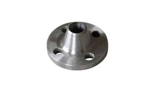
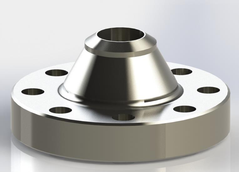
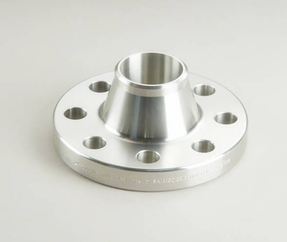
PN (“Pression Nominale”) is the nominal pressure class: a PN 25 flange is rated for about 25 bar at room temperature, derating as temperature rises per the material group tables. The old DIN system gave each flange type and class its own document number — for welding necks: DIN 2631 (PN 6), 2632 (PN 10), 2633 (PN 16), 2634 (PN 25) and 2635 (PN 40).
All dimensions in mm, per the standard. Smaller sizes are tabulated for two pipe series — the modern ISO pipe outside diameters and the older German DIN pipe series — which is why d1 and d3 appear on two lines for those sizes. The weight column is the standard’s published weight at 7.85 kg/dm³; we have added the lbs conversion.
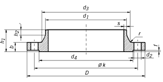
DIN Weld Neck Flange Dimension Reference — DIN 2634 (PN 25)
| d1: Pipe Outside Diameter (ISO / DIN series) D: Flange Outside Diameter b: Flange Thickness k: Bolt Circle (PCD) |
h1: Length Through Hub d3: Neck Diameter at Weld End s: Neck Wall Thickness r: Corner Radius |
h2: Hub (Taper) Height d4: Raised Face Diameter f: Raised Face Height d2: Bolt Hole Diameter |
| Pipe | Flange | Neck | Raised face | Screws | Weight | ||||||||||||
|---|---|---|---|---|---|---|---|---|---|---|---|---|---|---|---|---|---|
| (7.85 kg/dm³) | |||||||||||||||||
| Rated | d1 | D | b | k | h1 | d3 | s | r | h2 | d4 | f | Holes | Thread | d2 | kg | lbs | |
| Diameter | ISO Series | DIN Series | |||||||||||||||
| 15 | - | 20 | 95 | 16 | 65 | 38 | 30 | 2 | 4 | 6 | 45 | 2 | 4 | M 12 | 14 | 0.746 | 1.6 |
| 21.3 | - | 32 | |||||||||||||||
| 20 | - | 25 | 105 | 18 | 75 | 40 | 38 | 2.3 | 4 | 6 | 58 | 2 | 4 | M 12 | 14 | 1.06 | 2.3 |
| 26.9 | - | 40 | |||||||||||||||
| 25 | - | 30 | 115 | 18 | 85 | 40 | 42 | 2.6 | 4 | 6 | 68 | 2 | 4 | M 12 | 14 | 1.29 | 2.8 |
| 33.7 | - | 45 | |||||||||||||||
| 32 | - | 38 | 140 | 18 | 100 | 42 | 52 | 2.6 | 6 | 6 | 78 | 2 | 4 | M 16 | 18 | 1.88 | 4.1 |
| 42.4 | - | 56 | |||||||||||||||
| 40 | - | 44.5 | 150 | 18 | 110 | 45 | 60 | 2.6 | 6 | 7 | 88 | 3 | 4 | M 16 | 18 | 2.33 | 5.1 |
| 48.3 | - | 64 | |||||||||||||||
| 50 | - | 57 | 165 | 20 | 125 | 48 | 72 | 2.9 | 6 | 8 | 102 | 3 | 4 | M 16 | 18 | 2.82 | 6.2 |
| 60.3 | - | 75 | |||||||||||||||
| 65 | 76.1 | - | 185 | 22 | 145 | 52 | 90 | 2.9 | 6 | 10 | 122 | 3 | 8 | M 16 | 18 | 3.74 | 8.2 |
| 80 | 88.9 | - | 200 | 24 | 160 | 58 | 105 | 3.2 | 8 | 12 | 138 | 3 | 8 | M 16 | 18 | 4.75 | 10.5 |
| 100 | - | 108 | 235 | 24 | 190 | 65 | 128 | 3.6 | 8 | 12 | 162 | 3 | 8 | M 20 | 22 | 6.52 | 14.4 |
| 114.3 | - | 134 | |||||||||||||||
| 125 | - | 133 | 270 | 26 | 220 | 68 | 155 | 4 | 8 | 12 | 188 | 3 | 8 | M 24 | 26 | 9.07 | 20.0 |
| 139.7 | - | 162 | |||||||||||||||
| 150 | - | 159 | 300 | 28 | 250 | 75 | 182 | 4.5 | 10 | 12 | 218 | 3 | 8 | M 24 | 26 | 11.8 | 26 |
| 168.3 | - | 192 | |||||||||||||||
| (175) | 193.7 | - | 350 | 28 | 280 | 75 | 218 | 5.6 | 10 | 15 | 248 | 3 | 12 | M 24 | 26 | 13.4 | 30 |
| 200 | 219.1 | - | 360 | 30 | 310 | 80 | 244 | 6.3 | 10 | 16 | 278 | 3 | 12 | M 24 | 26 | 17 | 37 |
| 250 | - | 267 | 425 | 32 | 370 | 88 | 292 | 7.1 | 12 | 18 | 335 | 3 | 12 | M 27 | 30 | 24.4 | 54 |
| 273 | - | 298 | |||||||||||||||
| 300 | 323.9 | - | 485 | 34 | 430 | 92 | 352 | 8 | 12 | 18 | 395 | 4 | 16 | M 27 | 30 | 31.2 | 69 |
| 350 | 355.6 | - | 555 | 38 | 490 | 100 | 398 | 8 | 12 | 20 | 450 | 4 | 16 | M 30 | 33 | 47.2 | 104 |
| - | 368 | 44.2 | 97 | ||||||||||||||
| 400 | 406.4 | - | 620 | 40 | 550 | 110 | 452 | 8.8 | 12 | 20 | 505 | 4 | 16 | M 33 | 36 | 61.7 | 136 |
| - | 419 | 57.9 | 128 | ||||||||||||||
| (450) | 457 | - | 670 | 42 | 600 | 110 | 500 | 8.8 | 12 | 20 | 550 | 4 | 20 | M 33 | 36 | 71.9 | 159 |
| 500 | 508 | - | 730 | 44 | 660 | 125 | 558 | 10 | 12 | 20 | 615 | 4 | 20 | M 33 | 36 | 89.6 | 198 |
| 600 | 610 | - | 845 | 46 | 770 | 125 | 660 | 11 | 12 | 20 | 720 | 5 | 20 | M 36 | 39 | 104 | 229 |
| 700 | 711 | - | 960 | 46 | 875 | 125 | 760 | 13 | 20 | 24 | 820 | 5 | 24 | M 39 | 42 | 136 | 300 |
| 800 | 813 | - | 1085 | 50 | 990 | 135 | 865 | 14 | 22 | 24 | 930 | 5 | 24 | M 45 | 48 | 186 | 410 |
| 900 | 914 | - | 1185 | 54 | 1090 | 145 | 968 | 16 | 24 | 28 | 1030 | 5 | 28 | M 45 | 48 | 236 | 520 |
| 1000 | 1016 | - | 1320 | 58 | 1210 | 155 | 1070 | 18 | 24 | 28 | 1140 | 5 | 28 | M 52 | 56 | 307 | 677 |
Cross-class reference for DIN flange mating: outside diameter, bolt circle (PCD) and drilling for each DN across PN 6–PN 40 — useful when matching an unknown flange or checking whether two classes share a drilling.
| DN / BSP Size | PN 6 | PN 10 | PN 16 | PN 25 | PN 40 | Dimension |
|---|---|---|---|---|---|---|
| DN 10 | 75 | 90 | 90 | 90 | 90 | O.D. |
| 3/8" | 50 | 60 | 60 | 60 | 60 | PCD (bolt circle) |
| 4 x 11 | 4 x 14 | 4 x 14 | 4 x 14 | 4 x 14 | # of holes x diam. of holes | |
| DN 15 | 80 | 95 | 95 | 95 | 95 | O.D. |
| 1/2" | 55 | 65 | 65 | 65 | 65 | PCD (bolt circle) |
| 4 x 11 | 4 x 14 | 4 x 14 | 4 x 14 | 4 x 14 | # of holes x diam. of holes | |
| DN 20 | 90 | 105 | 105 | 105 | 105 | O.D. |
| 3/4" | 65 | 75 | 75 | 75 | 75 | PCD (bolt circle) |
| 4 x 11 | 4 x 14 | 4 x 14 | 4 x 14 | 4 x 14 | # of holes x diam. of holes | |
| DN 25 | 100 | 115 | 115 | 115 | 115 | O.D. |
| 1" | 75 | 85 | 85 | 85 | 85 | PCD (bolt circle) |
| 4 x 11 | 4 x 14 | 4 x 14 | 4 x 14 | 4 x 14 | # of holes x diam. of holes | |
| DN 32 | 120 | 140 | 140 | 140 | 140 | O.D. |
| 1 1/4" | 90 | 100 | 100 | 100 | 100 | PCD (bolt circle) |
| 4 x 14 | 4 x 18 | 4 x 18 | 4 x 18 | 4 x 18 | # of holes x diam. of holes | |
| DN 40 | 130 | 150 | 150 | 150 | 150 | O.D. |
| 1 1/2" | 100 | 110 | 110 | 110 | 110 | PCD (bolt circle) |
| 4 x 14 | 4 x 18 | 4 x 18 | 4 x 18 | 4 x 18 | # of holes x diam. of holes | |
| DN 50 | 140 | 165 | 165 | 165 | 165 | O.D. |
| 2" | 110 | 125 | 125 | 125 | 125 | PCD (bolt circle) |
| 4 x 14 | 4 x 18 | 4 x 18 | 4 x 18 | 4 x 18 | # of holes x diam. of holes | |
| DN 65 | 160 | 185 | 185 | 185 | 185 | O.D. |
| 2 1/2" | 130 | 145 | 145 | 145 | 145 | PCD (bolt circle) |
| 4 x 14 | 4 x 18 | 4 x 18 | 8 x 18 | 8 x 18 | # of holes x diam. of holes | |
| DN 80 | 190 | 200 | 200 | 200 | 200 | O.D. |
| 3" | 150 | 160 | 160 | 160 | 160 | PCD (bolt circle) |
| 4 x 18 | 8 x 18 | 8 x 18 | 8 x 18 | 8 x 18 | # of holes x diam. of holes | |
| DN 100 | 210 | 220 | 220 | 235 | 235 | O.D. |
| 4" | 170 | 180 | 180 | 190 | 190 | PCD (bolt circle) |
| 4 x 18 | 8 x 18 | 8 x 18 | 8 x 22 | 8 x 22 | # of holes x diam. of holes | |
| DN 125 | 240 | 250 | 250 | 270 | 270 | O.D. |
| 5" | 200 | 210 | 210 | 220 | 220 | PCD (bolt circle) |
| 8 x 18 | 8 x 18 | 8 x 18 | 8 x 26 | 8 x 26 | # of holes x diam. of holes | |
| DN 150 | 265 | 285 | 285 | 300 | 300 | O.D. |
| 6" | 225 | 240 | 240 | 250 | 250 | PCD (bolt circle) |
| 8 x 18 | 8 x 22 | 8 x 22 | 8 x 26 | 8 x 26 | # of holes x diam. of holes | |
| DN 175 | 315 | 315 | 330 | 350 | O.D. | |
| 7" | 270 | 270 | 280 | 295 | PCD (bolt circle) | |
| 8 x 22 | 8 x 22 | 12 x 26 | 12 x 30 | # of holes x diam. of holes | ||
| DN 200 | 320 | 340 | 340 | 360 | 375 | O.D. |
| 8" | 280 | 295 | 295 | 310 | 320 | PCD (bolt circle) |
| 8 x 18 | 8 x 22 | 12 x 22 | 12 x 26 | 12 x 30 | # of holes x diam. of holes | |
| DN 250 | 375 | 395 | 405 | 425 | 450 | O.D. |
| 10" | 335 | 350 | 355 | 370 | 385 | PCD (bolt circle) |
| 12 x 18 | 12 x 22 | 12 x 26 | 12 x 30 | 12 x 33 | # of holes x diam. of holes | |
| DN 300 | 440 | 445 | 460 | 485 | 515 | O.D. |
| 12" | 395 | 400 | 410 | 430 | 450 | PCD (bolt circle) |
| 12 x 22 | 12 x 22 | 12 x 26 | 16 x 30 | 16 x 33 | # of holes x diam. of holes | |
| DN 350 | 490 | 505 | 520 | 555 | 580 | O.D. |
| 14" | 445 | 460 | 470 | 490 | 510 | PCD (bolt circle) |
| 12 x 22 | 16 x 22 | 16 x 26 | 16 x 33 | 16 x 36 | # of holes x diam. of holes | |
| DN 400 | 540 | 565 | 580 | 620 | 660 | O.D. |
| 16" | 495 | 515 | 525 | 550 | 585 | PCD (bolt circle) |
| 16 x 22 | 16 x 26 | 16 x 30 | 16 x 36 | 16 x 39 | # of holes x diam. of holes | |
| DN 500 | 645 | 670 | 715 | 730 | 755 | O.D. |
| 20" | 600 | 620 | 650 | 660 | 670 | PCD (bolt circle) |
| 20 x 22 | 20 x 26 | 20 x 33 | 20 x 36 | 20 x 42 | # of holes x diam. of holes | |
| DN 600 | 755 | 780 | 840 | 845 | O.D. | |
| 24" | 705 | 725 | 770 | 770 | PCD (bolt circle) | |
| 20 x 24 | 20 x 27 | 20 x 33 | 20 x 36 | # of holes x diam. of holes |
DIN 2634 weld neck flanges are produced in every material family from our range — including the classic DIN grades C22.8 / P250GH — with ASTM and EN/Werkstoff designations, EN 10204 3.1 mill certificates, heat-number traceability and PMI on request:
| Material Family | Typical Grades (ASTM / EN) | Best suited to |
|---|---|---|
| Carbon Steel | A105 / P250GH (1.0460, ex C22.8) | General water, utility & hydrocarbon service |
| LTCS | A350 LF2 / LF3 | Low-temperature service, impact tested |
| Stainless Steel | 304/L (1.4301/1.4307), 316/L (1.4401/1.4404), 321 (1.4541), 310, 347, 410 | Corrosive process & hygienic service |
| 254 SMO | F44 (1.4547) | Seawater & high-chloride service |
| 904L | N08904 (1.4539) | Sulphuric & phosphoric acid service |
| Duplex / Super Duplex | 2205 (1.4462), 2507 (1.4410) | High strength + chloride resistance, offshore |
| Alloy Steel | A182 F1, F5, F9, F11, F22, F91 | High-temperature steam & refinery lines |
| Monel | 400 (2.4360) / K500 | Seawater, HF acid, marine |
| Inconel | 600 (2.4816), 625 (2.4856), 825 (2.4858) | High temperature, sour & oxidising media |
| Hastelloy | C276 (2.4819), C22 (2.4602) | Severely corrosive chemical service |
| Titanium | Gr. 2 (3.7035) / Gr. 5 (3.7165) | Chlorides, seawater; ≈42% lighter |
| Copper Nickel | 90/10 (C70600), 70/30 (C71500) | Marine & seawater cooling systems |
| Bimetal / Clad | CS base + SS/alloy overlay | Corrosion resistance at carbon-steel cost |
Prices are competitive and standard sizes are held in ready stock — use the Ask for Quote button or the inquiry form for today’s price list and stock position.
| DIN Standard | PN Class | Dimension Chart | EN 1092-1 Counterpart |
|---|---|---|---|
| DIN 2631 | PN 6 | DIN 2631 PN 6 Weld Neck Flange | EN 1092-1 Type 11 PN 6 |
| DIN 2632 | PN 10 | DIN 2632 PN 10 Weld Neck Flange | EN 1092-1 Type 11 PN 10 |
| DIN 2633 | PN 16 | DIN 2633 PN 16 Weld Neck Flange | EN 1092-1 Type 11 PN 16 |
| DIN 2634 | PN 25 | DIN 2634 PN 25 Weld Neck Flange (this page) | EN 1092-1 Type 11 PN 25 |
| DIN 2635 | PN 40 | DIN 2635 PN 40 Weld Neck Flange | EN 1092-1 Type 11 PN 40 |
Related references: Weld Neck Flanges overview · DIN 2527 Blind Flanges · All Flange Dimension Charts · Flange Weight Chart · EN 1092-1 Type 11 PN 25 Chart.
The tapered hub and full-penetration butt weld give the joint the strength and fatigue life of the pipe itself, and the weld is easily examined by radiography — the reason weld necks are specified where joint reliability matters.
DIN 2634 dimensions carried over into EN 1092-1 Type 11 — replacements for legacy German-standard plants bolt straight in, certified to either designation.
DIN 2634 carries roughly 25 bar cold — beyond PN 16 without the full weight of PN 40, on the same DIN-era dimensions that continue in EN 1092-1.
District heating, hot-water and thermal-oil circuits, moderate-pressure steam and condensate, chemical and food plants — especially replacements in legacy German-standard installations.
What is DIN 2634?
DIN 2634 is the German standard for welding neck (weld neck) flanges in nominal pressure class PN 25 — rated for roughly 25 bar at room temperature. It defines the flange outside diameter, thickness, bolt circle, drilling, neck dimensions and weights in millimetres for sizes DN 15 to DN 1000. The weld neck's tapered hub is butt-welded to the pipe, making it the standard construction for reliable, inspectable joints.
Is DIN 2634 still a valid standard?
Formally, no — DIN 2634 was withdrawn and superseded by the European standard EN 1092-1, which absorbed its dimensions as the Type 11 weld neck in PN 25. In practice the number is very much alive: drawings, spares lists and enquiries across the enormous installed base of DIN-era plants still cite DIN 2634 daily. We manufacture to the dimensions and certify to either designation.
Are DIN 2634 and EN 1092-1 Type 11 PN 25 interchangeable?
Yes, for practical purposes: EN 1092-1 carried the DIN dimensions over essentially unchanged, so a DIN 2634 flange mates with an EN 1092-1 Type 11 PN 25 flange of the same DN — same outside diameter, bolt circle and drilling. On critical joints, confirm details such as facing form and tolerances, which the EN standard defines slightly differently (DIN 2526 Form C corresponds in practice to EN Form B1).
What does PN 25 mean?
PN (“Pression Nominale”) is the nominal pressure class. A PN 25 flange is rated for a maximum working pressure of about 25 bar at room temperature, with the exact allowable pressure depending on the material group and falling as temperature rises. The DIN welding neck family ran PN 6, 10, 16, 25 and 40 — one DIN number per class, DIN 2631 through DIN 2635.
What do the letters in the dimension chart mean?
d1 is the pipe outside diameter (given for the ISO and old DIN pipe series), D the flange outside diameter, b the flange thickness, k the bolt circle (PCD), d2 the bolt hole diameter, h1 the length through hub, d3 the neck diameter at the weld end, s the neck wall thickness, r the corner radius, h2 the hub taper height, d4 the raised face diameter and f the raised face height. The lettered diagram above the chart shows each one.
Why do some sizes show two lines in the chart?
Because two pipe systems were in use in the DIN era: the modern ISO pipe outside-diameter series and the older German DIN pipe series. For the smaller sizes the standard tabulates both — the pipe OD (d1) and matching weld-end neck diameter (d3) differ between the series, while every other dimension of the flange is identical. State which pipe series you are welding to when ordering; modern projects almost always use the ISO series.
What sizes does DIN 2634 cover?
The chart on this page runs from DN 15 to DN 1000, per the standard. Within that range the smaller sizes carry the dual ISO/DIN pipe-series rows described above. For sizes or classes outside the DIN series, orders move to EN 1092-1 Type 11, which continues the same dimensional system.
How much does a DIN 2634 weld neck flange weigh?
The chart's weight column gives the standard's published weights at 7.85 kg/dm³ (carbon steel), to which we have added the lbs conversion: a DN 50 weighs about 2.82 kg (6.2 lbs), a DN 100 weighs about 6.52 kg (14.4 lbs), a DN 200 weighs about 17 kg (37 lbs), a DN 500 weighs about 89.6 kg (198 lbs). Stainless runs marginally heavier and titanium roughly 42% lighter; certified weights are issued on order.
How many bolts does a DIN 2634 flange take?
The Bolting columns give the count, metric thread and hole diameter per DN: a DN 15 takes 4 × M12, a DN 100 takes 8 × M20, a DN 400 takes 16 × M33 and a DN 1000 takes 28 × M52. The cross-class drilling matrix further down the page also lets you compare the drilling against the other PN classes when matching an unknown flange.
What facing does a DIN 2634 flange have?
The classic facing is a raised face to DIN 2526 Form C — the d4 and f columns in the chart give its diameter and height. It corresponds in practice to EN 1092-1 Form B1, so gaskets and mating faces carry over. Smooth finishes and other facing forms are machined on request.
Which gasket is used with DIN 2634 flanges?
EN 1514-1 sheet or spiral wound gaskets sized for PN 25; spiral wound preferred on steam and thermal-cycling duty. Always match the gasket to the facing and PN class of both flanges.
What materials are available for DIN 2634 flanges?
We manufacture them in carbon steel A105/P250GH — the modern equivalent of the classic DIN grade C22.8 (1.0460) — low-temperature A350 LF2, stainless steel 304/L, 316/L, 321, 310, 347 and 410 with their EN numbers (1.4301, 1.4404, 1.4541…), 254 SMO, 904L, duplex 2205 and super duplex 2507, alloy steel F1–F91, Monel, Inconel, Hastelloy, titanium, copper nickel and bimetal/clad — all with EN 10204 3.1 certificates.
Why choose a weld neck over a DIN slip-on or plate flange?
The weld neck's tapered hub and full-penetration butt weld give the joint the strength and fatigue life of the pipe itself, and the weld can be examined by radiography. DIN-era slip-on and plate flanges (DIN 2573/2576/2501 series) are cheaper and fine for undemanding, low-pressure duty, but for process lines, temperature cycling and critical media the welding neck construction is the engineering choice.
Which DIN standards cover the other flange types?
The DIN system gave each type its own numbers: DIN 2527 for blind flanges, DIN 2573/2576 for PN 6/PN 10 plate and slip-on flanges, DIN 2501 for the general dimension/drilling series, and DIN 2565/2566 for threaded flanges. The welding neck family is DIN 2631–2635 — one number per PN class — all now consolidated into EN 1092-1 with its type numbers.
Which standard do I use above PN 25?
Within the DIN welding neck family, DIN 2635 (PN 40) is the next and final step. Above PN 40 the DIN welding-neck series ends — higher classes are ordered to EN 1092-1 Type 11 (PN 63, PN 100 and up), which also carries the DIN dimensions for the classes below. See the EN 1092-1 charts linked on this page.
How are your DIN flanges tested and certified?
Every batch is dimensionally inspected against the standard, marked with size, class, material grade and heat number, and supplied with EN 10204 3.1 mill test certificates — issued to DIN or EN 1092-1 designation as your paperwork requires. PMI verification, ultrasonic and magnetic-particle examination, impact testing for low-temperature grades, NACE MR0175 compliance and third-party witness inspection by LR, BV, DNV, SGS, TÜV or IBR are available on request.
Can you make custom or non-standard DIN 2634 flanges?
Yes. Besides standard dimensions we machine special bores for either pipe series or non-standard walls, extended hubs and long weld neck versions, special facings and drilling, and flanges to customer drawings — including matching worn or undocumented legacy flanges from a sample or field measurements. Send the drawing or datasheet and we will quote to it.
Which industries buy DIN 2634 weld neck flanges?
District-heating utilities, chemical and food plants, thermal-oil and hot-water system builders, power-station auxiliary systems and maintenance teams serving legacy DIN-standard plants.
What information should I send with a DIN 2634 enquiry?
Size (DN) and quantity, the standard (DIN 2634 or EN 1092-1 Type 11 PN 25), pipe series (ISO or DIN) or wall thickness, facing, material grade, any impact-test or NACE requirement, and the certification and inspection you need. Tesco Steel & Engineering is an ISO 9001:2015 certified flange manufacturer and exporter in Mumbai, India, shipping worldwide with sea-worthy packing.