

'SHAPING INDUSTRIES WITH THE FINEST STEEL'
'SHAPING INDUSTRIES WITH THE FINEST STEEL'
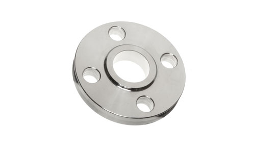
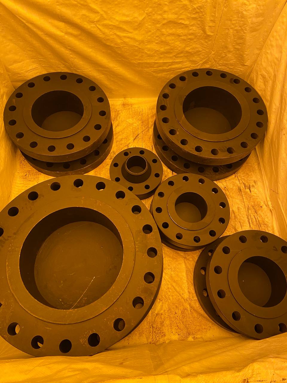
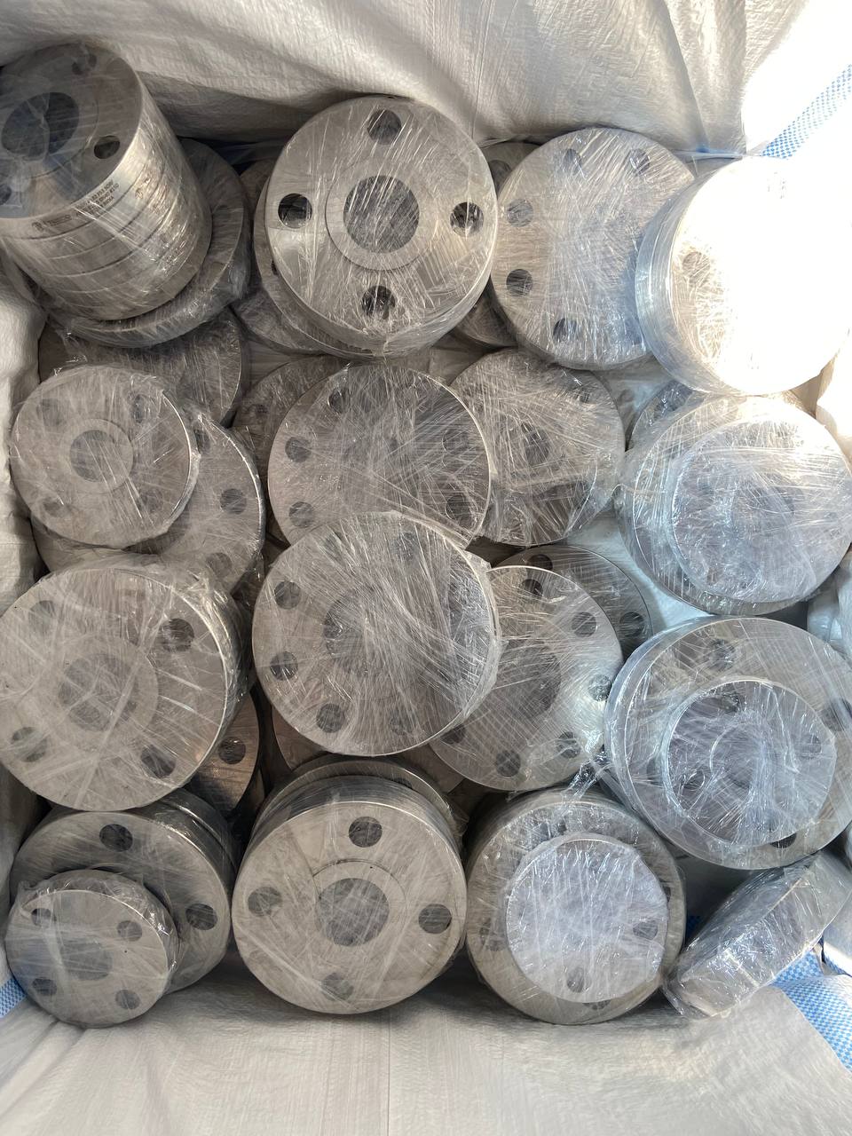
Tesco Steel & Engineering manufactures ASME B16.5 Class 600 slip-on flanges — the easy-alignment, lowest-cost welded flange: the bore slides over the pipe and two fillet welds complete the joint, no bevel needed. Sizes NPS ½–24 (DN 15–600), raised face 7 mm standard with flat face on request, bore sized to suit every pipe schedule. This page is the complete reference: the full dimension chart in mm with bore, bolt circles, bolting and weights, the pressure–temperature table in bar, the welding practice that makes slip-ons work, and every material grade we produce — from A105 and A350 LF2 to SS 316, alloy steel and duplex. ISO 9001:2015 certified, made in Mumbai, India — exported worldwide.
The slip-on flange earns its place on economics and forgiveness. The bore is machined a shade over the pipe OD, so the flange slides on without bevelling, aligns easily even on imperfect field cuts, and takes two fillet welds — one around the hub, one inside at the bore. That makes it the default welded flange for water treatment and distribution, HVAC and chilled-water headers, fire mains, low-pressure process and utility piping, pump, valve and tank nozzles, shipbuilding and offshore utilities. The honest trade-off: about two-thirds the strength and one-third the fatigue life of a weld neck of the same class — plenty for steady utility duty, not for critical or cyclic lines.
Fit-up is simple but has one rule: set the pipe end back from the flange face by the wall thickness plus about 3 mm, weld the hub fillet first (leg at least 1.4 × wall), then the internal fillet, and grind the internal weld flush if it stands proud of the face. Because the bore fits the pipe OD, no schedule needs specifying for the flange itself — a convenience unique to this type. The chart below carries every dimension against the lettered figure, with weights.
“Class 600” (also written 600 lb or #600, roughly PN 100) is a pressure–temperature rating class, not a working pressure. ASME B16.5 Table 2 gives the maximum allowable working pressure at each temperature for each material group — here in bar for the groups we ship most:
| Temperature °C | Group 1.1 — A105 / A350 LF2 | Group 2.1 — A182 F304 | Group 2.2 — A182 F316 |
|---|---|---|---|
| −29 to 38 | 102.1 | 99.3 | 99.3 |
| 100 | 93.2 | 84.4 | 86.3 |
| 150 | 90.2 | 77.0 | 79.0 |
| 200 | 87.6 | 71.3 | 73.3 |
| 250 | 83.9 | 66.8 | 68.9 |
| 300 | 79.6 | 63.2 | 65.2 |
| 350 | 75.1 | 60.7 | 62.6 |
| 400 | 69.4 | 58.9 | 60.9 |
| 450 | 57.5 | 57.5 | 58.8 |
Working pressure in bar (gauge) per ASME B16.5-2020 Table 2. The rating applies to the flange — confirm the fillet welds, bolting and gasket for the same duty, and always check the rating at your design temperature.
All dimensions in mm per ASME B16.5-2020 Tables 14 and 15. Letters follow the figure: D = flange outside diameter, B = flange thickness (excluding the 7 mm raised face), A = hub diameter, H = length through hub, ID = bore (pipe OD + clearance), G = raised face diameter, K = bolt circle (PCD), L = bolt hole diameter. Prefer it on paper? Download the full Class 600 slip on dimensions datasheet (PDF) — the same chart with the drawing, ratings, welding practice and ordering notes, ready for the workshop.
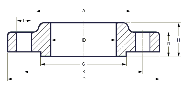
Slip On Flange Dimension Reference — ANSI / ASME B16.5
| Size in Inch | Size in mm | Flange OD | Thickness | Hub Ø | Length Through Hub | Bore | RF Diameter | PCD | No. of Studs | Hole Ø | Stud Size | Approx Weight (kg) |
|---|---|---|---|---|---|---|---|---|---|---|---|---|
| D | B | A | H | ID | G | K | — | L | — | |||
| 1/2 | 15 | 95 | 14.3 | 38 | 22 | 22.2 | 35 | 66.7 | 4 | 15.9 | 1/2 | 1.3 |
| 3/4 | 20 | 115 | 15.9 | 48 | 25 | 27.7 | 43 | 82.6 | 4 | 19.0 | 5/8 | 1.4 |
| 1 | 25 | 125 | 17.5 | 54 | 27 | 34.5 | 51 | 88.9 | 4 | 19.0 | 5/8 | 1.8 |
| 1 1/4 | 32 | 135 | 20.7 | 64 | 29 | 43.2 | 64 | 98.4 | 4 | 19.0 | 5/8 | 2.3 |
| 1 1/2 | 40 | 155 | 22.3 | 70 | 32 | 49.5 | 73 | 114.3 | 4 | 22.2 | 3/4 | 3.2 |
| 2 | 50 | 165 | 25.4 | 84 | 37 | 61.9 | 92 | 127.0 | 8 | 19.0 | 5/8 | 4.1 |
| 2 1/2 | 65 | 190 | 28.6 | 100 | 41 | 74.6 | 105 | 149.2 | 8 | 22.2 | 3/4 | 5.9 |
| 3 | 80 | 210 | 31.8 | 117 | 46 | 90.7 | 127 | 168.3 | 8 | 22.2 | 3/4 | 7.3 |
| 4 | 100 | 275 | 38.1 | 152 | 54 | 116.1 | 157 | 215.9 | 8 | 25.4 | 7/8 | 16.8 |
| 5 | 125 | 330 | 44.5 | 189 | 60 | 143.8 | 186 | 266.7 | 8 | 28.6 | 1 | 29 |
| 6 | 150 | 355 | 47.7 | 222 | 67 | 170.7 | 216 | 292.1 | 12 | 28.6 | 1 | 36 |
| 8 | 200 | 420 | 55.6 | 273 | 76 | 221.5 | 270 | 349.2 | 12 | 31.8 | 1 1/8 | 52 |
| 10 | 250 | 510 | 63.5 | 343 | 86 | 276.2 | 324 | 431.8 | 16 | 34.9 | 1 1/4 | 77 |
| 12 | 300 | 560 | 66.7 | 400 | 92 | 327 | 381 | 489.0 | 20 | 34.9 | 1 1/4 | 91 |
| 14 | 350 | 605 | 69.9 | 432 | 94 | 359.2 | 413 | 527.0 | 20 | 38.1 | 1 3/8 | 105 |
| 16 | 400 | 685 | 76.2 | 495 | 106 | 410.5 | 470 | 603.2 | 20 | 41.3 | 1 1/2 | 150 |
| 18 | 450 | 745 | 82.6 | 546 | 117 | 461.8 | 533 | 654.0 | 20 | 44.4 | 1 5/8 | 182 |
| 20 | 500 | 815 | 88.9 | 610 | 127 | 513.1 | 584 | 723.9 | 24 | 44.4 | 1 5/8 | 232 |
| 24 | 600 | 940 | 101.6 | 718 | 140 | 616 | 692 | 838.2 | 24 | 50.8 | 1 7/8 | 332 |
| Type | Joint | Character |
|---|---|---|
| Slip On (SO, this page) | Pipe through bore, two fillet welds | Lowest cost, easy alignment; utility & low-pressure process |
| Weld Neck (WN) | Full-penetration butt weld | Highest strength & fatigue life; critical / cyclic service |
| Socket Weld (SW) | Pipe in socket, one fillet weld | Smooth bore small-bore joint; NPS ½–3 |
| Threaded (TH) | NPT thread, no welding | For galvanised & no-hot-work lines; low pressure |
Class 600 slip-on flanges are produced in the material families below — each supplied with EN 10204 3.1 mill certificates, heat-number traceability and PMI on request:
| Material Family | Typical Flange Grades | Best suited to |
|---|---|---|
| Carbon Steel | ASTM A105 / A105N | Water, utility & general process piping |
| LTCS | ASTM A350 LF2 Cl.1 / Cl.2, LF3 | Low-temperature service, impact tested |
| Stainless Steel | A182 F304/L, F316/L, F321, F347 | Corrosive process & hygienic adjacent service |
| Alloy Steel | A182 F5, F9, F11, F12, F22, F91 | High-temperature steam & refinery service |
| Duplex / Super Duplex | A182 F51 (2205), F53 (2507), F55 | High strength + chloride resistance, offshore |
| Monel / Inconel / Hastelloy | 400, 600/625, C276 — on request | Severe corrosion & high temperature |
| Copper Nickel | 90/10 (C70600) — on request | Seawater & marine piping |
| EN / DIN Equivalents | P250GH (1.0460), 1.4301, 1.4401, 1.4404, 1.4571 | European specifications — on request |
Use the Ask for Quote button or the inquiry form for today’s price and delivery position.
| Pressure Class | Dimension Chart | Approx. A105 Rating @ 38 °C |
|---|---|---|
| Class 150 | Class #150 Slip On Flange | ≈285 psig |
| Class 300 | Class #300 Slip On Flange | ≈740 psig |
| Class 400 | Class #400 Slip On Flange | ≈990 psig |
| Class 600 | Class #600 Slip On Flange (this page) | ≈1480 psig |
| Class 900 | Class #900 Slip On Flange | ≈2220 psig |
| Class 1500 | Class #1500 Slip On Flange | ≈3705 psig |
Related references: Slip On Flanges overview · Socket Weld RF Flanges · All Flange Dimension Charts · Flange Weight Chart.
Less forging, no bevel preparation, no fit-up jigs — the slip-on is the economical welded joint wherever the duty allows it.
The clearance bore slides over field-cut pipe and tolerates small misalignment that a butt weld never would — a genuine site advantage.
The bore fits the pipe OD, which never changes with schedule — so stock one flange per size and class, whatever the wall thickness.
Water treatment and distribution, HVAC and chilled-water headers, fire-protection mains, low-pressure process and utility piping, pump, valve and tank nozzles, shipbuilding and offshore utility services.
What is a Class 600 slip-on flange?
A forged flange that slides over the pipe end — the bore is slightly larger than the pipe OD — and is secured with two fillet welds, one on the hub and one inside at the bore. No bevel preparation and easy alignment make it the lowest-cost welded flange for low- and medium-pressure process, water and utility piping. ASME B16.5 tabulates Class 600 slip-on flanges in NPS 1/2 to 24 (no 3-1/2).
What are the dimensions of a Class 600 slip-on flange?
They are tabulated in ASME B16.5-2020 Tables 14 and 15 and reproduced in full in the chart above: for each of the nineteen sizes, the flange OD, thickness, hub diameter, length through hub, bore, raised face diameter, bolt circle and bolting — all in millimetres — plus the approximate weight. A 6 in Class 600 slip-on flange, for example, is 355 mm OD and 47.7 mm thick (plus the 7 mm face) on a 292.1 mm bolt circle with twelve 1 in studs, at about 36 kg.
What pressure can a Class 600 slip-on flange handle?
The rating depends on material and temperature. For Group 1.1 materials such as A105 carbon steel, ASME B16.5 allows 102.1 bar (roughly 1480 psig) at 38 °C, derating with temperature — the full bar table for carbon and stainless groups is on this page. Remember the two fillet welds must suit the same duty; always confirm the rating at your design temperature.
Do I need to specify the pipe schedule for a slip-on flange?
No — and that is one of the type's conveniences. The bore is sized to the pipe OD plus clearance, and the pipe OD is the same for every schedule, so one flange fits them all. The schedule matters only for sizing the fillet welds; state it for the welder, not for the flange.
How is a slip-on flange welded?
Two fillet welds per ASME B31.3 Fig. 328.5.2B: slide the flange on, weld the hub fillet first with a leg at least 1.4 times the pipe wall, then the internal fillet at the bore. If the internal weld stands proud of the face, grind it flush so the gasket seats properly.
Why must the pipe be set back from the flange face?
Set the pipe end back from the face by the pipe wall thickness plus about 3 mm before welding. The set-back leaves room for the internal fillet weld so it does not project beyond the face and interfere with the gasket — the slip-on equivalent of the socket weld's 1.6 mm gap rule.
What is the difference between a slip-on and a weld neck flange?
Strength and fatigue life. A slip-on has roughly two-thirds the static strength of a weld neck of the same class and about one-third the fatigue life, because two fillet welds cannot match a full-penetration butt weld through a tapered hub. In exchange it costs less, needs no bevel and forgives misalignment — which is why utility and low-pressure process lines standardise on it, while critical and cyclic service goes weld neck.
What is the difference between a slip-on and a socket weld flange?
Both take the pipe into the flange, but the socket weld has a machined shoulder that locates the pipe and takes one external fillet, leaving a smooth bore — standardised only in NPS 1/2 to 3. The slip-on has a plain through-bore, takes two fillet welds and runs the full size range. In small bore the socket weld is the stronger joint; above NPS 3 the slip-on is the fillet-welded option.
When should a slip-on flange not be used?
In severe cyclic service, where the fillet welds fatigue long before a butt weld would; in high-temperature or hydrogen service, where codes prefer full-penetration welds; and in corrosive or hygienic service, where the crevice between pipe and bore traps product. In all of those, a weld neck flange is the right answer.
Does the thickness in the chart include the raised face?
No — at Class 400 and above the raised face is 7 mm, and the tabulated thickness B excludes it, while the length through hub H includes it. That is the reverse of the Class 150 and 300 convention, where the 2 mm face is included in the thickness — worth checking whenever you compare charts from different sources.
How much does a Class 600 slip-on flange weigh?
From the weight column in our chart: a 2 in weighs about 4.1 kg, a 6 in about 36 kg, a 12 in about 91 kg and a 24 in about 332 kg. These are approximate carbon-steel weights; the exact weight varies slightly with material.
What materials are available for slip-on flanges?
Carbon steel ASTM A105/A105N is the usual choice, with A350 LF2/LF3 for low temperature. Stainless A182 F304/L, F316/L, F321 and F347, alloy steel F5/F9/F11/F12/F22/F91 for high-temperature service, duplex F51 and super duplex F53/F55 — plus Monel 400, Inconel 600/625, Hastelloy C276 and copper-nickel 90/10 on request. EN equivalents such as P250GH, 1.4301 and 1.4404 are available — all with EN 10204 3.1 mill certificates.
What facing do these flanges come with?
A 7 mm raised face as standard, serrated to 125-250 microinch Ra (3.2-6.3 micrometre); flat face on request. State the facing with the enquiry.
Which gasket and bolts are used?
Spiral wound gaskets to ASME B16.20 or non-metallic gaskets to B16.21, with stud bolts and heavy hex nuts — A193 B7 / A194 2H for carbon steel, B8M Class 2 for stainless flanges. Counts, hole sizes and stud sizes per flange size are in the chart above; each hole is drilled 3 mm larger than its stud.
How are your slip-on flanges tested and certified?
Forged from certified bars and billets, normalised, quenched-and-tempered or solution annealed per the material specification, with the bore gauged on every piece. Dimensional inspection follows ASME B16.5 tolerances, face finish per MSS SP-6 and marking per MSS SP-25. Every batch ships with EN 10204 3.1 mill test certificates traceable by heat number; MPI/DPT, PMI, NACE MR0175, IBR and PED compliance and 3.2 endorsement are available on request.
What other names does this flange go by?
ANSI B16.5 600 lb SO flange, 600# slip-on raised face flange, SORF Class 600 and slip-on welding flange all describe the same product, at roughly PN 100 in metric terms. ANSI B16.5 and ASME B16.5 are also the same standard — custodianship moved from ANSI to ASME decades ago but the old name persists on drawings.
Class 600 and Class 300 slip-on flanges look identical in small bore — what differs?
At NPS 1/2 to 3 the two classes share the same flange OD and bolt circle at every size, so side by side they are hard to tell apart. The differences are the thickness (a 2 in grows from 22.4 to 25.4 mm), the raised face (2 mm at Class 300, 7 mm at Class 600) and of course the rating — 102.1 against 51.1 bar at 38 °C for A105. Check the marking, not the silhouette.