

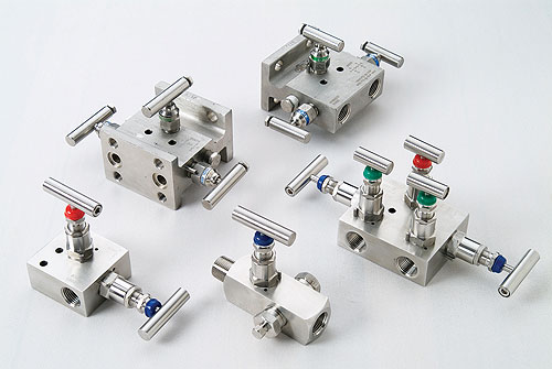
TES-LOK Manifold Valve Tube Fittings — multi-function instrumentation valve assemblies combining isolation, equalization, and blowdown in a single body. 2-Way · 3-Way · 5-Way · H-Type · T-Type · Coplanar · SS 316 · Brass · Monel · Inconel · Up to 6,000 PSI · ISO 9001:2015 certified.
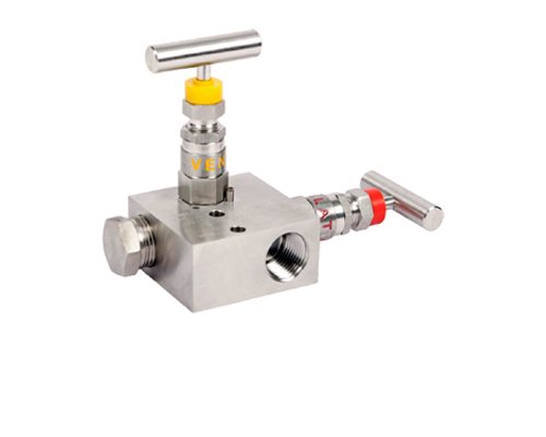
2-Way Manifold Valve
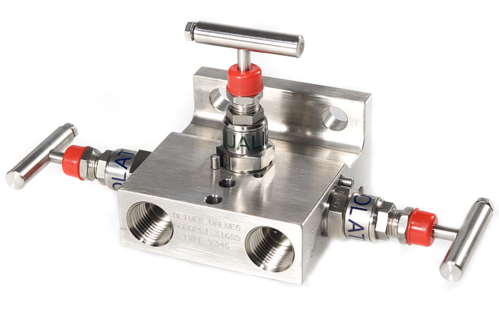
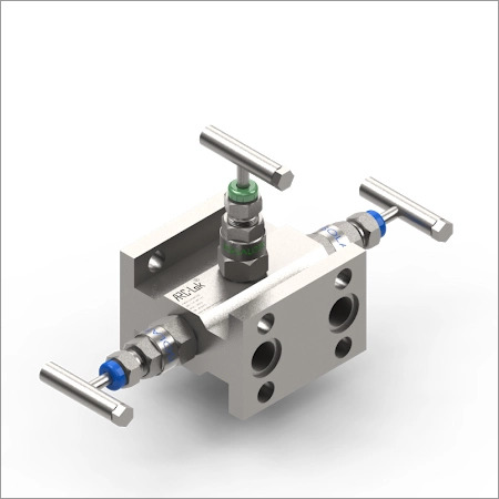
3-Way Manifold Valve
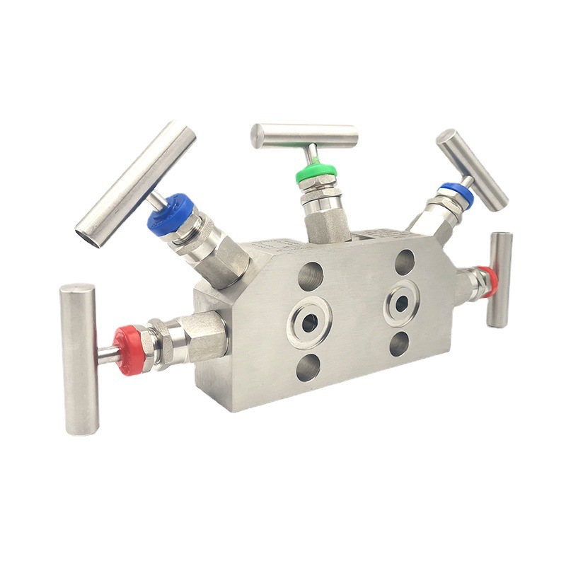
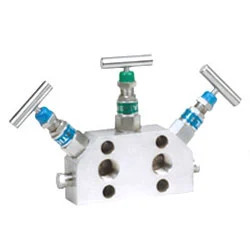
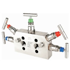
5-Way Manifold Valve
A manifold valve is a multi-function instrumentation valve assembly that combines two or more valve functions — isolation, equalization, and blowdown — into a single compact block body. It is the primary interface between the process piping (high-pressure and low-pressure tapping points) and a differential pressure (DP) transmitter, pressure gauge, or other instrument.
In a conventional DP measurement loop, separate isolation valves, equalizer valves, and blowdown valves would each require individual tube fittings, creating multiple potential leak points and a larger instrument-piping footprint. A manifold valve condenses all of these functions into one body with one instrument-side connection and one or two process-side connections — reducing leak joints, installation labour, and overall loop volume.
TES-LOK Manifold Valve Tube Fittings are manufactured by Tesco Steel & Engineering under the TES-LOK brand, the same brand behind the full range of double-ferrule compression tube fittings. The manifold body accepts TES-LOK compression tube ends on the process side, allowing direct connection to ¼" or ½" instrument impulse tubing without separate adapters. Coplanar variants bolt directly onto DP transmitter flanges (Rosemount/Emerson, Yokogawa) eliminating all impulse tubing between the manifold and transmitter.
The 3-valve manifold is the industry standard for DP transmitter service. It contains two isolation valves (one on the high-pressure leg, one on the low-pressure leg) and one equalization valve connecting the two legs inside the manifold body. The three operating modes are:
A 5-way manifold adds two blowdown (drain/vent) valves to the standard 3-valve configuration — one on the HP leg and one on the LP leg. These blowdown valves allow each impulse line to be independently vented or drained to atmosphere or a drain header without removing any tube connections.
5-way manifolds are preferred in offshore oil and gas, refinery, and other critical-service installations where impulse lines may accumulate liquid (in gas-service lines) or gas (in liquid-service lines), which would introduce measurement error. Periodic blowdown flushes the impulse lines and restores measurement accuracy. They are also used where positive isolation of the instrument is required for maintenance, combined with evidence of leak-free blowdown before opening.
| Configuration | Description | Process Connection | Instrument Connection | Typical Application |
|---|---|---|---|---|
| T-Type | Traditional / remote-mount; all process and instrument ports accessible from the top face | Compression tube or NPT/BSP (impulse line side) | NPT or BSP threaded (to instrument root valve or gauge) | Remote DP transmitter; pressure gauge manifolds; general instrumentation |
| H-Type | Block-and-bleed; inline between process flanges and transmitter; H-shaped flow path through the body | Flanged or compression tube (process side) | Flanged or NPT (transmitter side) | Direct-mount DP transmitter; pipeline installations; high-vibration service |
| Coplanar | Bolts directly onto the coplanar flange face of a DP transmitter — no impulse tubing between manifold and transmitter | Compression tube or NPT/BSP (process side, facing outward) | Coplanar flange bolt pattern (transmitter side) — Rosemount/Emerson, Yokogawa compatible | DP flow, level, and pressure transmitters; offshore; clean-service DP measurements |
| R-Type (2-Way) | Remote-seal; single isolation valve for connecting remote-seal DP or pressure transmitters via capillary | Compression tube or NPT | Capillary/diaphragm seal interface | Remote-seal pressure transmitters; viscous or fouling fluids |
Coplanar 3-Way Manifold — direct transmitter mount
H-Type 3-Way Manifold — block and bleed
Coplanar 5-Way Manifold — with blowdown valves
| Feature | 2-Way Manifold | 3-Way Manifold | 5-Way Manifold |
|---|---|---|---|
| Number of valves | 1 or 2 isolation | 2 isolation + 1 equalization | 2 isolation + 1 equalization + 2 blowdown |
| Instrument type served | Pressure gauge, single-leg pressure transmitter | DP transmitter, DP flow meter, DP level | DP transmitter — critical service, offshore, dirty service |
| Equalization function | No | Yes | Yes |
| Blowdown / vent function | No | No | Yes — independent HP and LP blowdown |
| In-line calibration | No (isolate only) | Yes — zero-check and span calibration | Yes — zero-check and span calibration |
| Configurations available | H-Type, T-Type, R-Type | H-Type, T-Type, Coplanar | H-Type, T-Type, Coplanar |
| Tube OD range | ¼" – ½" | ¼" – ½" | ¼" – ½" |
| Typical pressure rating (SS 316) | Up to 6,000 PSI | Up to 6,000 PSI | Up to 6,000 PSI |
| TES-LOK Manifold Valve Tube Fitting — Specifications | |
|---|---|
| Brand | TES-LOK (by Tesco Steel & Engineering) |
| Types | 2-Way (H-Type, T-Type, R-Type) · 3-Way (H-Type, T-Type, Coplanar) · 5-Way (H-Type, T-Type, Coplanar) |
| Tube OD (process side) | ¼" · 3/8" · ½" (imperial) · 6 mm · 10 mm · 12 mm (metric) |
| Thread connections | NPT ¼" · ½" · BSP ¼" · ½" · Coplanar flange (2-1/8" bolt circle) · Compression tube (double-ferrule) |
| Body materials | SS 316 / 316L (standard) · SS 304 · Brass · Monel 400 · Inconel 600 · Hastelloy C-276 |
| Stem / trim material | SS 316 (standard); matching CRA for corrosive service |
| Packing material | PTFE (standard, up to 260°C) · Grafoil graphite (high-temperature, up to 400°C) |
| Max. working pressure | 6,000 PSI (SS 316) · 3,000 PSI (Brass) |
| Pressure test | Hydrostatic to 1.5× working pressure |
| Temperature range | −196°C to +400°C (SS) · −29°C to +260°C (Brass) |
| Standards | ASTM D1710 · ASTM D3294 · ISO 9001:2015 |
| Certifications | ISO 9001:2015 · EN 10204 3.1 MTC available |
| Transmitter compatibility | Rosemount/Emerson 3051 series · Yokogawa EJA · ABB · Honeywell STD (coplanar bolt pattern) |
| Compatible tube fitting systems | TES-LOK (standard) · Swagelok · Parker A-LOK · Ham-Let (interchangeable ferrules) |
| Country of manufacture | India — ISO 9001:2015 certified facility |
| Criterion | Manifold Valve (TES-LOK) | Individual Needle/Globe Valves + Tubing |
|---|---|---|
| Number of fittings | 1 manifold body + 2 tube end connections | 3–5 separate valves + 6–10 tube fittings + tee and elbow fittings |
| Potential leak joints | 2–3 (process-side tube connections + instrument side) | 10–20+ (each fitting, valve body connection, and union) |
| Footprint | Compact — mounts directly on transmitter (coplanar) or small panel bracket | Larger — requires tubing runs between each valve and the transmitter |
| Installation time | Hours — single assembly bolted/tubed in one operation | Days — multiple fittings, valves, and tubing runs installed separately |
| Calibration sequence | Three-valve sequence built into the manifold body — no separate equalising spool required | Operator must operate multiple separate valves in correct sequence, risk of error |
| Maintenance | Single body — one point of maintenance; valve packing replaced in-situ on union-bonnet versions | Multiple valve bodies to inspect and maintain individually |
TES-LOK 3-way and 5-way manifolds consolidate all instrument-loop valve functions into one machined body — eliminating the multiple individual valves, tees, elbows, and tube runs required in a conventional instrument isolation assembly. Fewer components means fewer leak points and faster installation.
Coplanar manifolds bolt directly onto the face of Rosemount/Emerson 3051, Yokogawa EJA, and compatible DP transmitters using the standard 2-1/8" bolt circle flange pattern. The manifold-to-transmitter interface is a hard-metal-to-metal face seal — no gaskets, no impulse tubing, no additional connections between manifold and transmitter. This is the minimum possible leak-joint count for a DP loop.
The process-side connections use TES-LOK double-ferrule compression tube ends — the same bite-type ferrule mechanism used across the entire TES-LOK tube fitting range. No tube preparation, soldering, or welding required on the process side. Compatible with Swagelok, Parker A-LOK, and Ham-Let ferrules. Tube OD from ¼" to ½" imperial and 6 mm to 12 mm metric.
Available in SS 316/316L (standard), Monel 400 (HF acid, seawater), Inconel 600 (high-temperature oxidising), and Hastelloy C-276 (strongest general corrosion resistance). All CRA bodies are supplied with EN 10204 3.1 material test certificates, PMI-tested on request — meeting the documentation requirements of oil and gas, chemical, and pharmaceutical specifications.
The equalization valve in a TES-LOK 3-way or 5-way manifold is a precision needle valve with fine thread pitch — it opens gradually, allowing controlled pressure equalisation without spiking the transmitter sensing element. This protects expensive DP transmitters from diaphragm damage caused by sudden pressure surges during calibration switchover.
Every TES-LOK manifold valve is manufactured under an ISO 9001:2015 quality management system. Hydrostatic pressure test (1.5× working pressure) is performed on each assembly. EN 10204 3.1 material certificates, positive material identification (PMI), and third-party inspection (TPI) are available — meeting the documentation requirements of major oil and gas operator specifications.
| Industry | Typical Manifold Valve Application |
|---|---|
| Oil & Gas | DP flow measurement (orifice plate, annubar); wellhead pressure monitoring; offshore platform DP level measurement |
| Refinery & Petrochemical | Column differential pressure; reactor DP; heat exchanger fouling monitoring; analyser pressure conditioning |
| Power Generation | Boiler drum level DP; steam flow measurement; feedwater DP; turbine differential pressure |
| Chemical Process | Corrosive-fluid DP level; reagent tank level; pump differential pressure; filter DP monitoring |
| Pharmaceutical | Clean-room clean-in-place (CIP) differential pressure; sterile process DP; autoclave pressure isolation |
| Water & Wastewater | Flow measurement across weirs and flumes; pump station DP; filter press differential monitoring |
▶ What is a manifold valve used for?
A manifold valve is a multi-function instrumentation valve assembly used to connect differential pressure (DP) transmitters, pressure gauges, and other instruments to process lines. It combines isolation, equalization, and blowdown functions in a single compact body — replacing multiple individual valves. In a DP measurement loop, the manifold allows the instrument to be isolated from process pressure, equalized for zeroing and calibration, and the impulse lines blown down for cleaning — all without disturbing the tube connections.
▶ What is the difference between a 2-way, 3-way, and 5-way manifold valve?
A 2-way manifold valve has one or two isolation valves only — used for pressure gauge or single-leg instrument isolation. A 3-way manifold valve has two isolation valves plus one equalization valve — the standard for DP transmitter isolation and calibration. A 5-way manifold valve has the same three valves as a 3-way plus two additional blowdown valves — used when impulse lines need to be periodically drained or purged without removing tube connections, common in offshore and critical service.
▶ What is the difference between H-type and T-type manifold valves?
An H-type manifold (block-and-bleed) is designed for direct mounting between process flanges and the transmitter body, with an H-shaped internal flow path. A T-type manifold is a traditional remote-mount design where all ports face the same side — connected by impulse tubing to the process tapping points and to the transmitter. H-type is preferred for pipeline installations and high-vibration service; T-type for remote transmitter locations where impulse tubing is required.
▶ What is a coplanar manifold valve?
A coplanar manifold valve bolts directly onto the coplanar flange face of a DP transmitter — most commonly Rosemount/Emerson 3051 and similar instruments — using the standard 2-1/8" bolt circle pattern. This eliminates all impulse tubing between the manifold and transmitter. The process connections come out of the opposite face, connecting directly to the process tapping. Coplanar manifolds reduce potential leak joints, minimise dead-leg volume, and are preferred for hazardous area and offshore DP installations.
▶ How does a 3-valve manifold work?
A 3-valve manifold operates in three modes: Measure mode (both isolation valves open, equalization valve closed) — live process DP flows to the transmitter. Calibration mode (both isolation valves closed, equalization valve open) — both transmitter sides are at equal pressure for zero-check and calibration. Isolation mode (all three valves closed) — transmitter is fully isolated from process for maintenance. The equalization valve must be opened only after both isolation valves are fully closed to prevent transmitter over-range.
▶ Can TES-LOK manifold valves be used with compression tube fittings?
Yes. TES-LOK Manifold Valve Tube Fittings are available with double-ferrule compression tube end connections on the process side (¼" to ½" tube OD), allowing direct connection to instrument impulse tubing without adapters. The compression tube ends are compatible with Swagelok, Parker A-LOK, and Ham-Let tube fitting systems. The instrument side connection can be coplanar flange, NPT, or BSP depending on the transmitter interface.
▶ What materials are available for TES-LOK manifold valves?
TES-LOK Manifold Valve Tube Fittings are available in SS 316 (standard), SS 316L, SS 304, Brass (up to 3,000 PSI), Monel 400, Inconel 600, and Hastelloy C-276. Valve stem packing is PTFE standard or Grafoil graphite for high-temperature and steam service. All materials are supplied with EN 10204 3.1 material test certificates.
▶ What is the maximum pressure rating for a TES-LOK manifold valve?
TES-LOK Manifold Valve Tube Fittings are rated up to 6,000 PSI working pressure in SS 316 bodies at ambient temperature. Brass-body manifolds are rated up to 3,000 PSI. All manifold valves are hydro-tested to 1.5× working pressure before dispatch. Contact Tesco Steel for high-pressure variants for wellhead and hydraulic service.
2-Way · 3-Way · 5-Way · H-Type · T-Type · Coplanar · SS 316 · Brass · CRA · Up to 6,000 PSI
ISO 9001:2015 certified · EN 10204 3.1 MTC · Fast delivery worldwide