

Groove & Tongue Flanges | Large T&G Flanges | Small T&G Flanges | ASME B16.5 Dimensions | T&G vs RF vs RTJ | All Material Grades | Standards & Specs
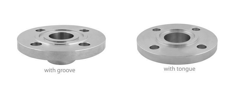
A Groove and Tongue flange (also written as Tongue and Groove or T&G) is a matched pair of flanges where one flange has a raised ring — the tongue — and the mating flange has a matching machined depression — the groove. When bolted together, the tongue seats precisely into the groove, fully confining the gasket within the groove cavity on all four sides.
This gasket confinement is the defining advantage of T&G flanges: unlike a raised face (RF) connection where the gasket is exposed at its outer edge, the T&G groove prevents the gasket from blowing out under high internal pressure or being eroded by high-velocity fluid flow. The joint also self-centres — the tongue locates the groove eliminating misalignment during assembly.
Tesco Steel & Engineering manufactures Groove and Tongue flanges per ASME B16.5 (½″–24″ NB, Class 150–2500) in both Large T&G and Small T&G configurations, across all standard materials from Carbon Steel ASTM A105 to exotic alloys including Hastelloy C276 and Titanium Grade 2. All flanges are ISO 9001:2015 certified with EN 10204 3.1 MTCs.
ASME B16.5 defines two distinct tongue and groove configurations that differ in the radial width of the tongue/groove ring:
| Feature | Large Tongue & Groove | Small Tongue & Groove |
|---|---|---|
| Ring radial width | Wider — larger gasket seating area | Narrower — compact ring dimensions |
| Tongue OD (Y) vs Groove OD (W) | Larger Y and W values (see dimension table) | Smaller Y and W values (see dimension table) |
| Primary use | Standard process piping flanges, most common T&G application | Vessel nozzle covers, heat exchanger channel flanges, compact joints |
| Gasket area | Larger gasket area → lower seating stress required | Smaller gasket area → higher seating stress (good for harder gaskets) |
| ASME B16.5 reference | Tables E2.2 (tongue) and E2.1 (groove) | Tables E2.4 (tongue) and E2.3 (groove) |
| Interchangeability | Large tongue mates only with Large groove | Small tongue mates only with Small groove |
| Face Type | Gasket | Confinement | Self-Centering | Matched Pair? | Typical Use |
|---|---|---|---|---|---|
| Raised Face (RF) | Spiral wound / sheet | None — exposed outer edge | No | No — RF mates with RF | Standard general process service |
| Flat Face (FF) | Full-face rubber/PTFE | None | No | No — FF mates with FF | Mating with cast iron or glass-lined equipment |
| Tongue & Groove (T&G) | Ring gasket (SW, solid, soft) | Full — all four sides | Yes — tongue locates in groove | Yes — tongue + groove pair | Hazardous, toxic, high-pressure, high-velocity service |
| Male & Female (M&F) | Ring gasket | Partial — 3 sides | Yes | Yes — male + female pair | Pump nozzles, similar to T&G but more common in some APIs |
| Ring Type Joint (RTJ) | Solid metal ring (R/RX/BX) | Full — metal-to-metal | Yes — ring locates in groove | No — RTJ mates with RTJ (same ring groove) | High-pressure wellhead, Class 900+ HP/HT service |
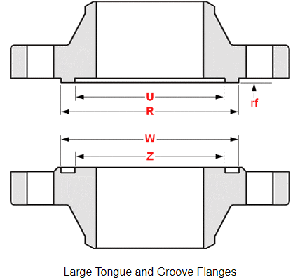
Dimension key: R = Groove inner diameter (bore side) | U = Reference diameter | W = Groove outer diameter | Z = Groove depth
| NPS | R (mm) | U (mm) | W (mm) | Z (mm) |
|---|---|---|---|---|
| ½ | 35.05 | 25.40 | 36.57 | 23.87 |
| ¾ | 42.92 | 33.27 | 44.45 | 31.75 |
| 1 | 50.80 | 38.10 | 52.32 | 36.57 |
| 1¼ | 63.50 | 47.75 | 65.02 | 45.97 |
| 1½ | 73.15 | 53.84 | 74.67 | 52.32 |
| 2 | 91.94 | 73.15 | 93.72 | 71.37 |
| 2½ | 104.64 | 85.85 | 106.42 | 84.07 |
| 3 | 127.00 | 107.95 | 128.52 | 106.42 |
| 3½ | 139.70 | 120.65 | 141.22 | 119.12 |
| 4 | 157.22 | 131.82 | 158.75 | 130.04 |
| 5 | 185.67 | 160.27 | 187.45 | 158.75 |
| 6 | 215.90 | 190.50 | 217.42 | 188.97 |
| 8 | 269.74 | 238.25 | 271.52 | 236.47 |
| 10 | 323.85 | 285.75 | 325.37 | 284.22 |
| 12 | 381.00 | 342.90 | 382.52 | 341.37 |
| 14 | 412.75 | 374.65 | 414.27 | 373.12 |
| 16 | 469.90 | 425.45 | 471.42 | 423.92 |
| 18 | 533.40 | 488.95 | 534.92 | 487.42 |
| 20 | 584.20 | 533.40 | 585.72 | 531.87 |
| 24 | 692.15 | 641.35 | 693.67 | 639.82 |
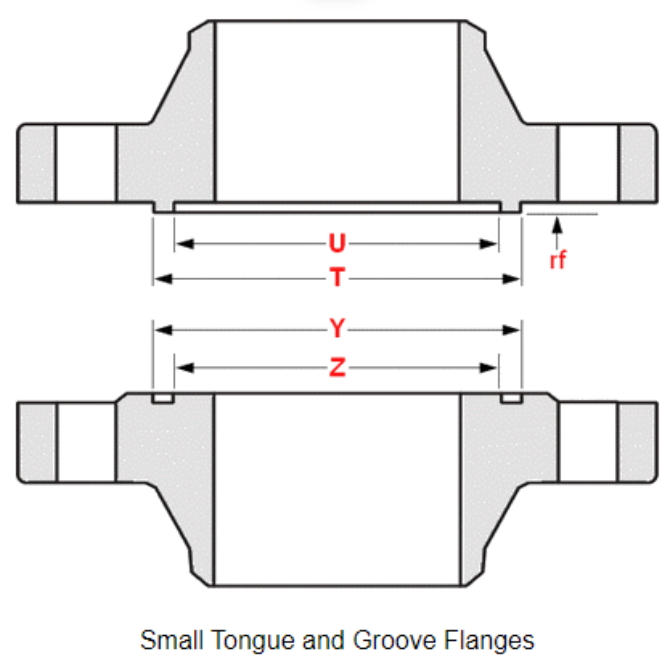
Dimension key: T = Tongue inner diameter | U = Reference diameter | Y = Tongue outer diameter | Z = Tongue height
| NPS | T (mm) | U (mm) | Y (mm) | Z (mm) |
|---|---|---|---|---|
| ½ | 35.05 | 25.40 | 36.57 | 23.87 |
| ¾ | 42.92 | 33.27 | 44.45 | 31.75 |
| 1 | 47.75 | 38.10 | 49.27 | 36.57 |
| 1¼ | 57.15 | 47.75 | 58.67 | 45.97 |
| 1½ | 63.50 | 53.84 | 65.02 | 52.32 |
| 2 | 82.55 | 73.15 | 84.07 | 71.37 |
| 2½ | 95.25 | 85.85 | 96.77 | 84.07 |
| 3 | 117.34 | 107.95 | 119.12 | 106.42 |
| 3½ | 130.04 | 120.65 | 131.82 | 119.12 |
| 4 | 144.52 | 131.82 | 146.05 | 130.04 |
| 5 | 172.97 | 160.27 | 174.75 | 158.75 |
| 6 | 203.20 | 190.50 | 204.72 | 188.97 |
| 8 | 254.00 | 238.25 | 255.52 | 236.47 |
| 10 | 304.80 | 285.75 | 306.32 | 284.22 |
| 12 | 361.95 | 342.90 | 363.47 | 341.37 |
| 14 | 393.70 | 374.65 | 395.22 | 373.12 |
| 16 | 447.54 | 425.45 | 449.32 | 423.92 |
| 18 | 511.04 | 488.95 | 512.82 | 487.42 |
| 20 | 558.80 | 533.40 | 560.32 | 531.87 |
| 24 | 666.75 | 641.35 | 668.27 | 639.82 |
| Material | ASTM / UNS Grade | Key Properties | Typical Service |
|---|---|---|---|
| Carbon Steel | ASTM A105 | UTS 485 MPa, general purpose | Utility, steam, non-corrosive process |
| LTCS | ASTM A350 LF2 | Impact tested to −46°C | LNG, cold utilities, cryogenic |
| Alloy Steel | ASTM A182 F5, F9, F11, F22, F91 | Cr-Mo, high-temp strength to 650°C | Power generation, HP steam |
| SS 304 / 304L | ASTM A182 F304 / F304L | 18Cr-8Ni, UTS 515 MPa | Mild corrosive, food, pharma |
| SS 316 / 316L | ASTM A182 F316 / F316L | 16Cr-10Ni-2Mo, pitting resistant | Marine, chemical, chloride environments |
| SS 321 / 347 | ASTM A182 F321 / F347 | Ti or Nb stabilised, sensitisation-resistant | High-temperature steam, boilers |
| SS 310 | ASTM A182 F310 | 25Cr-20Ni, high-temp oxidation | Furnaces, high-temperature gas |
| 904L | ASTM A182 F904L (UNS N08904) | 20Cr-25Ni-4.5Mo-1.5Cu | H₂SO₄, phosphoric acid, seawater |
| Duplex 2205 | ASTM A182 F51 (UNS S31803/S32205) | PREN ≥ 35, UTS 620 MPa | Offshore, desalination, heat exchangers |
| Super Duplex 2507 | ASTM A182 F53 (UNS S32750) | PREN ≥ 40, UTS 795 MPa | High-chloride, deep offshore |
| Monel 400 | ASTM B564 (UNS N04400) | 67Ni-30Cu, HF acid resistant | Hydrofluoric acid, marine, brine |
| Inconel 625 | ASTM B564 (UNS N06625) | 21Cr-9Mo-3.65Nb, UTS 830 MPa | Subsea, aggressive acid, aerospace |
| Incoloy 825 | ASTM B564 (UNS N08825) | 21Cr-38Ni-3Mo-2.2Cu, SCC resistant | Sour gas, phosphoric/sulphuric acid |
| Hastelloy C276 | ASTM B564 (UNS N10276) | 16Cr-16Mo-4W, broadest acid resistance | HCl, H₂SO₄, wet chlorine, FGD |
| Hastelloy C22 | ASTM B564 (UNS N06022) | 21Cr-13Mo-3W, oxidising + reducing | Mixed acid, pharma, chlorination |
| Copper Nickel 90/10 | C70600 (UNS) | Biofouling resistant, seawater | Naval, offshore, condenser nozzles |
| Titanium Gr. 1 / Gr. 2 | ASTM B381 F-1 / F-2 | CP titanium, excellent seawater and halide resistance | Seawater, bleach plants, wet chlorine |
| Nickel 200 / 201 | UNS N02200 / N02201 | 99.6% Ni, caustic resistant | Caustic soda production, food processing |
| Industry | Typical Application | Why T&G is Specified | Material |
|---|---|---|---|
| Oil & Gas | Sour gas wellhead nozzles, HP separator flanges | Gasket blow-out prevention in HP H₂S service | A182 F316L, F51, Inconel 625 |
| Petrochemical | Reactor manways, column nozzles, heat exchanger channel covers | Confined gasket for toxic hydrocarbon service | A105, A182 F316L, Hastelloy C276 |
| Power Generation | HP/HT steam generator nozzles, turbine inlet flanges | High sealing integrity at elevated pressure and temperature | A182 F11, F22, F91 |
| Chemical Processing | Acid reactor flanges, column reboiler connections | Gasket confinement prevents acid leakage/splash hazard | A182 F316L, Hastelloy C276, Titanium Gr.2 |
| Offshore & Marine | Subsea wellhead flanges, seawater heat exchanger nozzles | High-integrity seal in deep-sea HP service | Duplex F51, Super Duplex F53, CuNi C70600 |
| Pharmaceutical | Sterile process vessel nozzles, CIP system connections | No gasket-face gap to harbour contamination; repeatable reassembly | A182 F316L (ASME-BPE), Hastelloy C22 |
| Pulp & Paper | Bleach plant digester nozzles, chlorine dioxide system flanges | Contained seal for corrosive bleaching chemical service | A182 F316L, Hastelloy C276, Titanium Gr.2 |
| Cryogenic / LNG | LNG cold box flanges, cryogenic storage vessel nozzles | Gasket confinement prevents seal failure during thermal cycling | A350 LF2, A182 F304L, Monel 400 |
| Category | Standard | Scope |
|---|---|---|
| Dimensional | ASME B16.5 | Pipe flanges and flanged fittings — Class 150–2500, incl. T&G dimensions (Appendix E) |
| Dimensional | ASME B16.47 | Large diameter flanges NPS 26–60, Series A and B |
| Dimensional | MSS SP-44 | Steel pipeline flanges, alternate large-diameter standard |
| Dimensional | EN 1092-1 | European flanges — steel, PN 2.5–400 |
| Dimensional | DIN 86029 | DIN tongue and groove flanges for marine / ship applications |
| Material — CS | ASTM A105 | Carbon steel forgings for piping components |
| Material — LTCS | ASTM A350 LF2 | Low-temperature carbon steel forgings |
| Material — Alloy/SS | ASTM A182 | Alloy and stainless steel flanged fittings and forgings |
| Material — Nickel Alloys | ASTM B564 | Nickel and nickel alloy forgings |
| Material — Titanium | ASTM B381 | Titanium and titanium alloy forgings |
| Gaskets | ASME B16.20 | Metallic gaskets for pipe flanges — spiral wound, ring joint |
| Inspection | EN 10204 3.1 / 3.2 | Material test certificate — 3.1 works certification, 3.2 third-party witness |
| Piping Code | ASME B31.3 | Process piping design and material requirements |
| Pressure Vessel | ASME VIII Div. 1 | Vessel nozzle flange design basis |
Countries we export to: Kuwait, UAE, Germany, Saudi Arabia, West Africa, Iraq, Congo, Mexico, Bahrain, Canada, Philippines, Thailand, Kenya, Oman, Malaysia, Turkey, Qatar, Sudan, Netherlands, Nigeria, Lithuania, Gabon, Russia, Vietnam, Angola, Indonesia, UK, Yemen, Italy, USA, Venezuela, Spain, Iran, Kazakhstan, Algeria, Jordan, Colombia, Libya, Chile, Peru, South Africa, Israel, Denmark, Norway, France, Brazil, Poland, Greece, Egypt, New Zealand and 50+ more countries.
Domestic markets: Mumbai, Delhi, Bangalore, Hyderabad, Ahmedabad, Chennai, Kolkata, Surat, Pune, Jaipur, Gujarat, Maharashtra, Rajasthan, Tamil Nadu, Telangana, Karnataka, Uttar Pradesh, West Bengal and all major Indian industrial hubs.
Common questions about tongue and groove (T&G) flanges — their design, ASME B16.5 dimensions, gaskets, materials, and when to specify them. Answers are written to match the structured-data (FAQ schema) on this page.
A Tongue and Groove (T&G) flange is a matched pair of flanges — one has a raised ring (the tongue) and the mating flange has a matching machined depression (the groove). When bolted together, the tongue locates into the groove and fully confines the gasket inside the groove cavity. This prevents gasket blow-out, self-centres the joint, and gives superior leak integrity compared with a raised-face (RF) connection.
Per ASME B16.5 both types use the same principle but differ in the radial width of the tongue/groove ring. Large T&G has wider tongue and groove dimensions, giving a bigger gasket seating area — used for standard process-piping flanges. Small T&G has a narrower ring width — typically used for vessel nozzle covers, pump covers, and compact joint designs where a smaller face is acceptable.
No. Tongue and groove flanges are a matched pair — a tongue flange must always mate with a groove flange of the same NPS, pressure class, and T&G type (large or small). A tongue flange bolted to a raised-face (RF) flange would have the tongue bearing on the RF face instead of seating the gasket, creating uneven bolt load and almost certain leakage.
Gaskets are sized to fit inside the groove — the gasket OD matches the groove OD and the ID matches the groove ID. Common types: spiral-wound gaskets (inner ring only — no centring ring needed, as the groove self-centres), solid metal ring gaskets, and soft ring gaskets (PTFE, CAF, graphite). Because the gasket is confined on all four sides, much higher seating stress is achieved, allowing harder gasket materials.
Per ASME B16.5 the tongue height (equal to the groove depth) is 1.65 mm (1/16") for Class 150 and 300 — the same as the raised-face height. For Class 400, 600, 900, 1500, and 2500 the tongue height is 6.35 mm (1/4"). This height is included in the minimum flange thickness for Class 150/300 but is additional to the minimum thickness for the higher classes.
Both are paired face types with a projection on one flange and a recess on the other. The difference is the gasket bearing area: in Tongue and Groove (T&G) the gasket contacts the bottom of the groove only (fully confined). In Male and Female (M&F) the male face is flat and raised and the female face is a recess — the gasket sits on the male face inside the female recess. T&G gives slightly better gasket confinement; M&F is more common for pipe flanges, while T&G is more common for nozzle and heat-exchanger connections.
Carbon steel T&G flanges are forged to ASTM A105 (standard service) or ASTM A350 LF2 (low temperature to −46°C / −50°F), with the face machined to ASME B16.5 T&G dimensions. Alloy steel uses ASTM A182 (F5, F9, F11, F22, F91); stainless steel uses ASTM A182 (F304/304L, F316/316L, F321, F347, F904L). All supplied with EN 10204 3.1 material test certificates.
Specify T&G over raised-face (RF) flanges when: (1) the fluid is highly hazardous or toxic and gasket blow-out must be prevented; (2) very high differential pressure across the face requires confined gasket seating; (3) high fluid velocity could erode or wash out an exposed gasket; (4) the joint is on a heat-exchanger channel cover or pump casing needing reliable re-assembly after maintenance; or (5) the process/company specification mandates a confined-gasket face for the service category.
Yes. Tesco Steel supplies T&G flanges in Duplex 2205 (ASTM A182 F51, UNS S31803/S32205), Super Duplex 2507 (F53, UNS S32750), and Zeron 100 (F55, UNS S32760). These are commonly specified for offshore oil & gas heat-exchanger nozzles, seawater cooling systems, and desalination-plant connections where both high strength and chloride-corrosion resistance are needed.
Per ASME B16.5 the gasket-seating contact face is finished to 125–250 AARH (3.2–6.3 µm Ra) serrated for most gasket types; spiral-wound or sheet gaskets use 125–250 AARH concentric or phonographic serrations. For solid metal ring gaskets a smoother 63–125 AARH (1.6–3.2 µm Ra) is required on the groove floor. Tongue-height and groove-depth tolerances are held to ±0.38 mm (±0.015") per ASME B16.5.
| Standard | ASME B16.5, B16.47, EN 1092-1, DIN 86029 |
| Types | Large T&G, Small T&G |
| Size Range | ½″ – 24″ NB (DN 15 – DN 600) |
| Pressure Class | 150, 300, 600, 900, 1500, 2500 |
| PN Rating | PN 6 – PN 400 |
| Tongue Height | 1.65 mm (Cl.150/300) / 6.35 mm (Cl.400+) |
| Finish | 125–250 AARH serrated |
| Cert | EN 10204 3.1 / 3.2 |
Note: No centering ring needed on spiral wound gaskets — groove provides centring.