

Tesco Steel & Engineering manufactures orifice plates — thin, precision-bored metal plates clamped between a pair of orifice flanges to measure flow by differential pressure. As fluid passes through the calibrated bore it speeds up and its pressure drops; the pressure difference across the plate is proportional to the flow rate. Supplied in concentric, eccentric, segmental, and quadrant bore types to ISO 5167 / ASME, with a stamped tab and vent/drain hole. SS 304/316/321, Monel, Inconel, Hastelloy. Class 150 to 2500, PN1 to PN400. ISO 9001:2015 certified. Made in India.

Orifice Plates — Concentric, Eccentric & Segmental
An orifice plate works as a set with orifice flanges (which hold it and carry the pressure tappings). Tesco Steel & Engineering manufactures orifice plates in all bore types to ISO 5167 / ASME in the full material range — dimensioned per the tables below; see also the flange dimensions charts.
| Type | Bore | Best For |
|---|---|---|
| Concentric | Round hole centred in the pipe | Clean liquids, gases & steam — the standard, most common type |
| Eccentric | Round hole offset to the pipe wall | Fluids with entrained solids, condensate, or gas; bore set low (liquids) or high (gas) to let the second phase pass |
| Segmental | Segment (part-circle) opening | Slurries & heavily contaminated fluids that would block a round bore |
| Quadrant / Conical Edge | Rounded or conical bore edge | Viscous fluids & low Reynolds-number (low-flow) service |
| Orifice Plates are available in the following specifications: | |
|---|---|
| Size | 1/2"NB to 56"NB |
| Class | 150#, 300#, 3000#, 6000#, 9000# |
| Sch (Schedule) | XS, XXS, STD & Schedule 20, 40, 80, 160 |
| Pressure Ratings | PN 1 - PN 400 |
| Stainless Steel Orifice Plates | ASTM A 182 F - 304 / 304H / 304L / 316 / 316H / 316L / 316Ti, 309, 310, 317L, 321, 347, 904L |
| Duplex Steel Orifice Plates | ASTM A 182 - F 51, F 53, F 55 |
| Alloy Steel Orifice Plates | ASTM A 182 - F5, F9, F11, F21, F22 & F91 |
| Carbon Steel Orifice Plates | ASTM A 105 |
| Low Temp. Carbon Steel Orifice Plates (LTCS Orifice Flanges Flanges) | A 350 LF2 |
| Copper Nickel (Cu-Ni) Orifice Plates | C70600, 90/10, C71500, 70/30, C71640 |
| Nickel Orifice Plates | UNS N02200, UNS N02201 |
| Monel Orifice Plates | UNS N04400, UNS N05500, Alloy 20 |
| Inconel Orifice Plates | UNS N06600, UNS N06601, UNS N06625, UNS N08800, UNS N08810, UNS N08825 |
| Hastelloy Orifice Plates | UNS N10276, UNS N06022, UNS N10665, UNS N06455 |
| Titanium Orifice Plates | Gr. 1, Gr. 2, Gr. 3, DTH 3.7035, DTH 3.7055 |
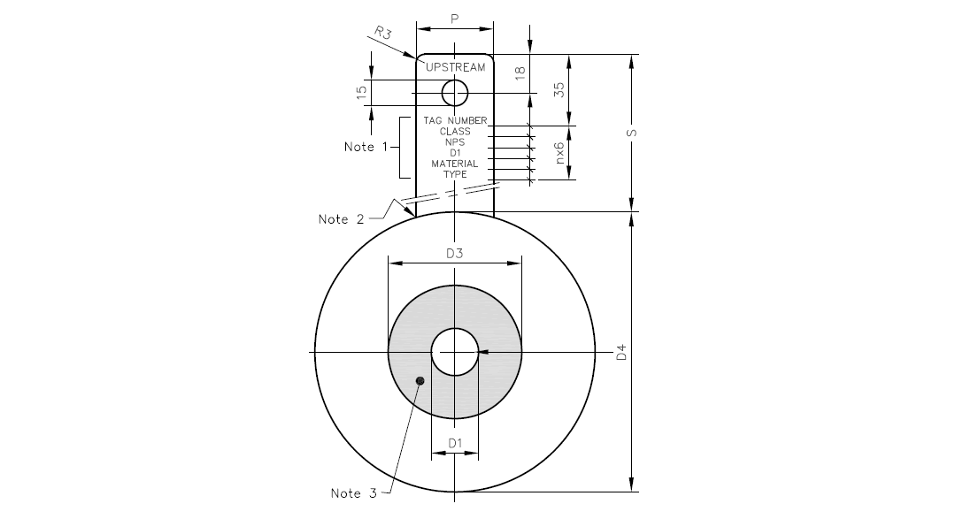
Orifice Plate Dimension Diagram
Orifice Plate Dimensions Detail
| NPS | DIA D3 |
L | N | P | T |
| 1/2 | 13 | 0.24 | 1.5 | 30 | 1.5 |
| 3/4 | 19 | 0.34 | 1.5 | 30 | 1.5 |
| 1 | 25 | 0.42 | 2 | 30 | 2 |
| 1.1/2 | 40 | 0.64 | 3 | 30 | 3 |
| 2 | 51 | 1 | 6 | 30 | 3 |
| 3 | 76 | 1.5 | 8 | 40 | 3 |
| 4 | 102 | 1.5 | 10 | 40 | 5 |
| 6 | 152 | 1.5 | 15 | 40 | 5 |
| 8 | 202 | 3.5 | 15 | 40 | 7 |
| 10 | 253 | 3.5 | 19 | 45 | 7 |
| 12 | 302 | 3.5 | 20 | 45 | 10 |
| 14 | 341 | 6 | 20 | 45 | 10 |
| 16 | 392 | 6 | 21 | 50 | 11 |
| 18 | 443 | 8 | 23 | 50 | 13 |
| 20 | 494 | 8 | 25 | 50 | 16 |
| 24 | 595 | 10 | 29 | 60 | 18 |
| NPS | ASME B16.5 Flange Class | |||||
| 150 | 300 | 600 | 900 | 1500 | 2500 | |
| S | ||||||
| 1/2 | 110 | 110 | 110 | 115 | 115 | 120 |
| 3/4 | 110 | 110 | 110 | 115 | 115 | 120 |
| 1 | 110 | 115 | 115 | 120 | 120 | 125 |
| 1.1/2 | 110 | 120 | 120 | 125 | 125 | 130 |
| 2 | 110 | 115 | 115 | 125 | 125 | 130 |
| 3 | 115 | 120 | 120 | 125 | 135 | 140 |
| 4 | 115 | 125 | 125 | 130 | 140 | 150 |
| 6 | 115 | 120 | 130 | 135 | 145 | 170 |
| 8 | 120 | 125 | 135 | 145 | 155 | 170 |
| 10 | 120 | 130 | 145 | 145 | 165 | 190 |
| 12 | 125 | 135 | 140 | 145 | 165 | 195 |
| 14 | 130 | 140 | 145 | 150 | 175 | |
| 16 | 130 | 145 | 150 | 155 | 180 | |
| 18 | 130 | 145 | 155 | 160 | 195 | |
| 20 | 135 | 150 | 155 | 165 | 205 | |
| 24 | 135 | 160 | 165 | 190 | 2205 | |
| NPS | ASME B16.5 Flange Class | |||||
| 150 | 300 | 600 | 900 | 1500 | 2500 | |
| DIA | ||||||
| D4 | ||||||
| 1/2 | 48 | 54 | 54 | 64 | 64 | 70 |
| 3/4 | 57 | 67 | 67 | 70 | 70 | 77 |
| 1 | 67 | 73 | 73 | 80 | 80 | 86 |
| 1.1/2 | 86 | 96 | 96 | 99 | 99 | 118 |
| 2 | 105 | 111 | 111 | 143 | 143 | 146 |
| 3 | 137 | 149 | 149 | 168 | 175 | 197 |
| 4 | 175 | 181 | 194 | 206 | 209 | 235 |
| 6 | 222 | 250 | 266 | 289 | 282 | 317 |
| 8 | 279 | 307 | 320 | 358 | 352 | 387 |
| 10 | 339 | 361 | 399 | 434 | 434 | 475 |
| 12 | 409 | 422 | 456 | 497 | 520 | 549 |
| 14 | 450 | 485 | 491 | 519 | 577 | |
| 16 | 513 | 539 | 564 | 573 | 640 | |
| 18 | 548 | 596 | 611 | 637 | 703 | |
| 20 | 605 | 653 | 681 | 697 | 754 | |
| 24 | 716 | 773 | 789 | 836 | 899 | |
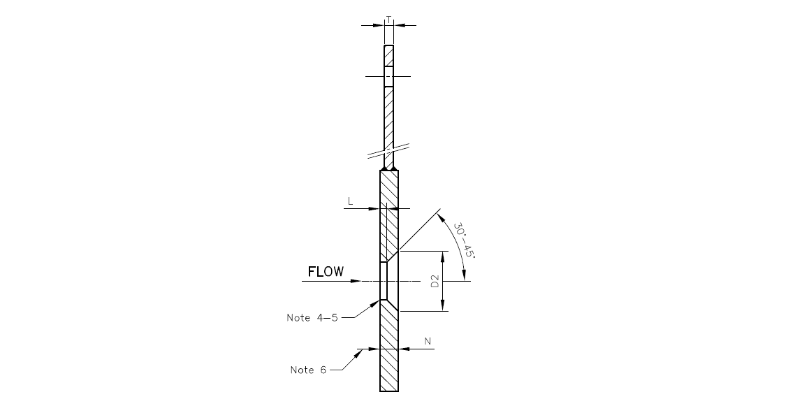
Calibrated bore and sharp upstream edge machined to ISO 5167 / ASME for accurate, repeatable differential-pressure flow measurement.
Concentric, eccentric, segmental, and quadrant/conical bores for clean fluids, two-phase, slurry, and viscous service.
Projecting tab stamped with bore, material, and orientation, with vent or drain hole positioned for the fluid.
SS 304/316/321, Monel, Inconel, Hastelloy, and A105 for gas, steam, and corrosive or high-temperature flows.
Supplied to match our orifice flanges as a complete metering assembly.
Made to ISO 5167 / ASME or your data sheet, with the bore calculated for your flow, certified with EN 10204 3.1 MTC.
| Material | Properties | Typical Use |
|---|---|---|
| SS 316 / 316L | Excellent — chloride resistant | General process, chemical & offshore metering |
| SS 304 / 304L | Good corrosion resistance | Water, air & mild process |
| SS 321 | Stabilised for high temperature | High-temperature steam & gas |
| Monel 400 | Excellent in HF & marine media | HF, seawater & reducing media |
| Inconel / Hastelloy | High-temperature & acid resistance | High-temperature & aggressive flows |
| Industry | Typical Use | Why Orifice Plate |
|---|---|---|
| Oil & Gas | Gas & liquid flow / custody metering | Standard, robust DP element |
| Refinery & Petrochemical | Process flow measurement | All bore types; full material range |
| Power Generation | Steam & feed-water flow | SS 321 high-temperature plates |
| Chemical Plants | Corrosive & slurry flow | Segmental/eccentric; Monel/Inconel |
| Gas Distribution | Pipeline gas measurement | ISO 5167 concentric plates |
| Water & Utilities | Water & utility flow | Economical SS plates |
| Pharma / Food | Clean process flow | Clean SS 316 plates |
| Marine & Offshore | Topside flow metering | SS / alloy corrosion resistance |
Q1. What is an orifice plate?
An orifice plate is a thin, precision-bored metal plate clamped between a pair of orifice flanges to measure flow by differential pressure. As fluid passes through the calibrated bore it accelerates and its pressure drops; the pressure difference across the plate, sensed through the flange tappings, is proportional to the flow rate. It is the most common primary element in flow measurement.
Q2. What are the types of orifice plate?
Concentric (round centred bore — the standard for clean fluids), eccentric (bore offset to the wall, for fluids with entrained gas or solids), segmental (part-circle opening, for slurries), and quadrant/conical-edge (for viscous, low-Reynolds-number flow). The type is chosen for the fluid and any second phase.
Q3. How does an orifice plate work?
It restricts the flow, so the fluid speeds up through the bore and its static pressure drops downstream. A differential-pressure transmitter reads the pressure difference between the upstream and downstream flange tappings, and the flow rate is calculated as proportional to the square root of that differential pressure, following ISO 5167.
Q4. Which way does an orifice plate face?
The sharp (square) edge of the bore must face upstream, into the flow, with the bevel (if any) downstream. The stamped tab should be readable, the vent hole positioned at the top (to pass gas in a liquid line) and the drain hole at the bottom (to pass condensate in a gas line). Installing the plate backwards causes large measurement errors.
Q5. What are the vent and drain holes for?
A small vent hole at the top of the bore lets trapped gas pass in a liquid line, and a drain hole at the bottom lets condensate pass in a gas line, preventing a second phase from building up against the plate and disturbing the measurement. The hole is sized and positioned per the service.
Q6. What standard governs orifice plates?
ISO 5167 is the principal standard for orifice-plate flow measurement (bore, edge sharpness, tappings, and calculation), often used with AGA 3 for gas. The plate is dimensioned to fit ASME B16.5 orifice flanges. We manufacture plates to ISO 5167 / ASME with the bore calculated for your flow data.
Q7. What materials are orifice plates made from?
SS 304/316/316L and 321, Monel, Inconel, Hastelloy, and carbon steel (A105). The grade is chosen for the fluid, pressure, and temperature — for example SS 321 for high-temperature steam and Monel/Inconel/Hastelloy for corrosive flows.
Q8. Do orifice plates come with orifice flanges?
They work as a set: the orifice flanges hold the plate and carry the pressure tappings, and the orifice plate is the bored primary element. We supply plates and flanges separately or as a complete metering assembly with bolting, gaskets, and the calculated bore, certified with EN 10204 3.1 MTC.