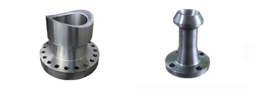
A Nipoflange (also written Nipo Flange or Nipoflanges) is a one-piece integrally reinforced forged fitting that combines a Nipolet branch outlet on the run side with a weld-neck flange on the branch side. The run side is saddle-welded directly onto the header (run) pipe — just like a standard Nipolet — providing integral weld reinforcement per MSS SP-97. The branch side presents a standard ASME B16.5 weld-neck flange face, giving a fully flanged, demountable branch connection without requiring a separate tee fitting.
Tesco Steel & Engineering manufactures Nipoflanges in India across a comprehensive range of materials, sizes, and pressure classes. Our Nipoflanges are 100% hydrostatically tested and supplied with material test certificates (MTCs) in accordance with EN 10204 3.1 / 3.2.
A Nipoflange is defined under MSS SP-97 as an integrally reinforced forged branch outlet fitting. It is the industry solution when engineers need a branch connection that is:
| Feature | Nipoflange | Weldoflange |
|---|---|---|
| Governing Standard | MSS SP-97 | MSS SP-97 |
| Run Side Geometry | Nipolet-style (smaller saddle) | Weldolet-style (larger saddle) |
| Typical Branch Size | ½″ – 6″ NB | 2″ – 16″ NB |
| Header Size Range | ¾″ – 36″ NB | 4″ – 36″ NB |
| Best Use Case | Small high-pressure branches (sampling, instruments, bypass) | Larger branch connections (sub-headers, tie-ins) |
| Reinforcement | Integral (nipolet pad) | Integral (weldolet contour) |
| Branch Side | ASME B16.5 weld-neck flange | ASME B16.5 weld-neck flange |
Nipoflanges are available in all major piping material groups. Material selection is based on operating temperature, process fluid corrosivity, and design code requirements:
| Material Group | Grade / Specification | Key Properties |
|---|---|---|
| Carbon Steel | ASTM A105 | General purpose, −29°C to +427°C, most economical |
| LTCS (Low Temp Carbon Steel) | ASTM A350 LF2 Cl.1 / Cl.2 | Charpy impact tested to −46°C, cryogenic service |
| Stainless Steel — Austenitic | ASTM A182 F304, F304L, F316, F316L, F321, F347, F904L | Corrosion resistant, food & chemical service |
| Alloy Steel (Cr-Mo) | ASTM A182 F5, F9, F11, F22, F91 | High temperature creep resistance, power generation |
| Duplex Stainless Steel | ASTM A182 F51 (UNS S31803) | High strength + pitting resistance, offshore |
| Super Duplex | ASTM A182 F53 (S32750), F55 (S32760) | Seawater, sour gas, chloride environments |
| Nickel 200 / 201 | UNS N02200 / N02201 | Caustic soda, food processing |
| Monel 400 / K500 | UNS N04400 / N05500 | Seawater, HF acid, marine |
| Inconel 625 / 825 | UNS N06625 / N08825 | High temp oxidation, sour gas, nuclear |
| Hastelloy C276 / C22 | UNS N10276 / N06022 | Wet chlorine, FGD, mixed acids |
| Copper Nickel | C70600 (90/10), C71500 (70/30) | Seawater piping, marine heat exchangers |
| Titanium | Gr. 2 (R50400), Gr. 5 (R56400) | Chemical processing, bleaching, desalination |
| Standard | Scope |
|---|---|
| MSS SP-97 | Design and dimensions of integrally reinforced forged branch outlet fittings (Nipoflange, Weldoflange, Elboflange) |
| ASME B16.5 | Flange face dimensions, bolt-hole patterns, pressure-temperature ratings (Class 150–2500, sizes up to 24″) |
| ASME B16.47 | Large diameter flanges above 24″ NB (Series A: MSS SP-44; Series B: API 605) |
| ASME B31.3 | Process piping branch reinforcement calculations |
| ASME B31.1 | Power piping branch reinforcement calculations |
| ASTM A105 | Carbon steel forging material specification |
| ASTM A182 | Alloy and stainless steel forging material specification |
| EN 1092-1 | European flanges (metric PN rating system) |
| Industry | Typical Nipoflange Applications | Common Material |
|---|---|---|
| Oil & Gas — Upstream | Wellhead bypass lines, sampling connections, chemical injection quills | A105, A350 LF2, F316L |
| Refinery / Downstream | Pressure relief line take-offs, hydrocarbon process branches, instrument connections | A105, F11, F22, F316 |
| Offshore / Subsea | Topside vent and drain branches, umbilical take-off points, seawater service lines | F51, F53, C70600, Titanium |
| Petrochemical | Reactor vessel branches, high-pressure loop connections, secondary line tie-ins | F316L, F321, F347, Hastelloy |
| Power Generation | Steam main branch connections, condenser feed lines, attemperator connections | F22, F91, A105 |
| Chemical Processing | Acid service branch lines, corrosive fluid sampling, vent connections | F316L, Hastelloy C276, Titanium Gr.2 |
| Water Treatment / Desalination | Dosing and injection lines, pressure monitoring branches | F316L, Duplex F51, C70600 |
| LNG / Cryogenic | Low temperature branch connections on LNG pipelines | A350 LF2, F304L |
Replaces tee + two flanges + two welds with a single forged unit. Every eliminated joint is a potential leak point removed from the system.
Eliminates a separate tee fitting and spool pieces. Ideal for congested pipe racks, platforms, and modules where space is critical.
The forged nipolet pad provides branch reinforcement per ASME B31.3 / B31.1 — no separate reinforcing pad welding required.
The weld-neck flange branch side allows the branch piping to be fully removed for maintenance, inspection, or replacement without cutting the header.
Available through ASME B16.5 Class 2500# (PN 420). Suitable for the highest-pressure applications in subsea, wellhead, and high-pressure steam systems.
Fewer components means fewer procurement items, fewer inspection certificates, and fewer man-hours in the field — reducing total installed cost significantly.
| Nipoflanges are available in the following specifications: | |
|---|---|
| Size | 1/2"NB to 56"NB |
| Class | 150#, 300#, 3000#, 6000#, 9000# |
| Sch (Schedule) | XS, XXS, STD & Schedule 20, 40, 80, 160 |
| Pressure Ratings | PN 1 - PN 400 |
| Stainless Steel Nipoflanges | ASTM A 182 F - 304 / 304H / 304L / 316 / 316H / 316L / 316Ti, 309, 310, 317L, 321, 347, 904L |
| Duplex Steel Nipoflanges | ASTM A 182 - F 51, F 53, F 55 |
| Alloy Steel Nipoflanges | ASTM A 182 - F5, F9, F11, F21, F22 & F91 |
| Carbon Steel Nipoflanges | ASTM A 105 |
| Low Temp. Carbon Steel Nipoflanges (LTCS Nipoflanges Flanges) | A 350 LF2 |
| Copper Nickel (Cu-Ni) Nipoflanges | C70600, 90/10, C71500, 70/30, C71640 |
| Nickel Nipoflanges | UNS N02200, UNS N02201 |
| Monel Nipoflanges | UNS N04400, UNS N05500, Alloy 20 |
| Inconel Nipoflanges | UNS N06600, UNS N06601, UNS N06625, UNS N08800, UNS N08810, UNS N08825 |
| Hastelloy Nipoflanges | UNS N10276, UNS N06022, UNS N10665, UNS N06455 |
| Titanium Nipoflanges | Gr. 1, Gr. 2, Gr. 3, DTH 3.7035, DTH 3.7055 |
| Other Services | Hot Dip Galvanized (GI) Nipoflanges Sand Blasting on Nipoflanges Shot Peening on Nipoflanges Epoxy Coating on Nipoflanges FBE Coating on Nipoflanges |
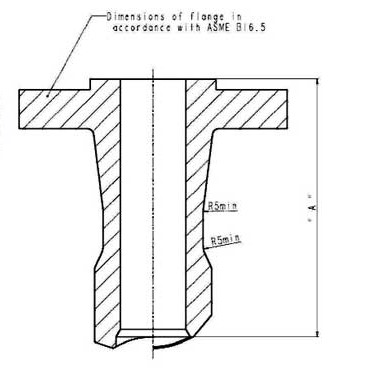
| RATING | NOMINAL PIPE SIZE FROM 3/4" TO 36" | |||||
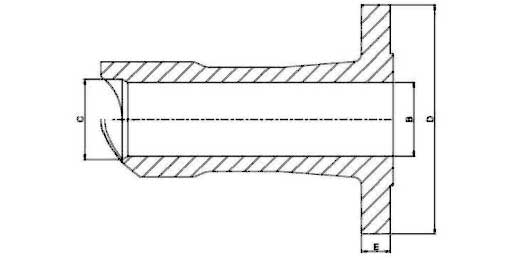
| Bore schedule | B | C | D | E | Weight [kg] | |
| 150# | STD | 15,8 | 18,5 | 88,9 | 11,2 | 0,9 |
| XS | 13,8 | 17,6 | 0,9 | |||
| 160 | 11,7 | 11,7 | 0,9 | |||
| XXS | 6,4 | 6,4 | 0,9 | |||
| 300# | Bore schedule | B | C | D | E | Weight [kg] |
| STD | 15,8 | 18,5 | 95,3 | 14,3 | 1,2 | |
| XS | 13,8 | 17,6 | 1,2 | |||
| 160 | 11,7 | 11,7 | 1,2 | |||
| XXS | 6,4 | 6,4 | 1,2 | |||
| 600# | Bore schedule | B | C | D | E | Weight [kg] |
| STD | 15,8 | 18,5 | 95,3 | 14,3 | 1,3 | |
| XS | 13,8 | 17,6 | 1,3 | |||
| 160 | 11,7 | 11,7 | 1,3 | |||
| XXS | 6,4 | 6,4 | 1,3 | |||
| 900# | Bore schedule | B | C | D | E | Weight [kg] |
| STD | 15,8 | 18,5 | 120,6 | 22,4 | 2,4 | |
| XS | 13,8 | 17,6 | 2,4 | |||
| 160 | 11,7 | 11,7 | 2,4 | |||
| XXS | 6,4 | 6,4 | 2,4 | |||
| 1500# | Bore schedule | B | C | D | E
| Weight [kg] |
|
| STD | 15,8 | 18,5 | 120,6 | 22,4 | 2,4 | |
| XS | 13,8 | 17,6 | 2,4 | |||
| 160 | 11,7 | 11,7 | 2,4 | |||
| XXS | 6,4 | 6,4 | 2,4 | |||
| 2500# | Bore schedule | B
| C |
D |
E |
Weight [kg] |
|
| STD | 15,8 | 18,5 | 133,4 | 30,2 | 3,6 | |
| XS | 13,8 | 17,6 | 3,6 | |||
| 160 | 11,7 | 11,7 | 3,6 | |||
| XXS | 6,4 | 6,4 | 3,6 | |||
| RATING | NOMINAL PIPE SIZE FROM 3/4" TO 36" | |||||
| Bore schedule | B | C | D | E | Weight [kg] | |
| 150# | STD | 21 | 23,8 | 98,6 | 12,7 | 1,2 |
| XS | 18,9 | 22,8 | 1,2 | |||
| 160 | 15,6 | 15,6 | 1,4 | |||
| XXS | 11,1 | 11,1 | 1,5 | |||
| 900# | Bore schedule | B | C | D | E | Weight [kg] |
| STD | 21 | 23,8 | 117,4 | 15,8 | 1,7 | |
| XS | 18,9 | 22,8 | 1,9 | |||
| 160 | 15,6 | 15,6 | 2 | |||
| XXS | 11,1 | 11,1 | 2,1 | |||
| 900# | Bore schedule | B | C | D | E | Weight [kg] |
| STD | 21 | 23,8 | 117,4 | 15,8 | 2 | |
| XS | 18,9 | 22,8 | 2,1 | |||
| 160 | 15,6 | 15,6 | 2,2 | |||
| XXS | 11,1 | 11,1 | 2,2 | |||
| 900# | Bore schedule | B | C | D | E | Weight [kg] |
| STD | 21 | 23,8 | 130 | 25,4 | 3,1 | |
| XS | 18,9 | 22,8 | 3,2 | |||
| 160 | 15,6 | 15,6 | 3,2 | |||
| XXS | 11,1 | 11,1 | 3,3 | |||
| 1500# | Bore schedule | B | C | D | E | Weight [kg] |
| STD | 21 | 23,8 | 130 | 25,4 | 3,1 | |
| XS | 18,9 | 22,8 | 3,2 | |||
| 160 | 15,6 | 15,6 | 3,2 | |||
| XXS | 11,1 | 11,1 | 3,3 | |||
| 2500# | Bore schedule | B | C | D | E | Weight [kg] |
| STD | 21 | 23,8 | 139,7 | 31,8 | 4,4 | |
| XS | 18,9 | 22,8 | 4,5 | |||
| 160 | 15,6 | 15,6 | 4,5 | |||
| XXS | 11,1 | 11,1 | 4,6 | |||
| RATING | NOMINAL PIPE SIZE FROM 3/4" TO 36" | |||||
| Bore schedule | B | C | D | E | Weight [kg] | |
| STD | 15,8 | 18,5 | 88,9 | 11,2 | 0,9 | |
| XS | 13,8 | 17,6 | 0,9 | |||
| 160 | 11,7 | 11,7 | 0,9 | |||
| XXS | 6,4 | 6,4 | 0,9 | |||
| Bore schedule | B | C | D | E | Weight [kg] | |
| STD | 15,8 | 18,5 | 95,3 | 14,3 | 1,2 | |
| XS | 13,8 | 17,6 | 1,2 | |||
| 160 | 11,7 | 11,7 | 1,2 | |||
| XXS | 6,4 | 6,4 | 1,2 | |||
| Bore schedule | B | C | D | E | Weight [kg] | |
| STD | 15,8 | 18,5 | 95,3 | 14,3 | 1,3 | |
| XS | 13,8 | 17,6 | 1,3 | |||
| 160 | 11,7 | 11,7 | 1,3 | |||
| XXS | 6,4 | 6,4 | 1,3 | |||
| Bore schedule | B | C | D | E | Weight [kg] | |
| STD | 15,8 | 18,5 | 120,6 | 22,4 | 2,4 | |
| XS | 13,8 | 17,6 | 2,4 | |||
| 160 | 11,7 | 11,7 | 2,4 | |||
| XXS | 6,4 | 6,4 | 2,4 | |||
| Bore schedule | B | C | D | E | Weight [kg] | |
| STD | 15,8 | 18,5 | 120,6 | 22,4 | 2,4 | |
| XS | 13,8 | 17,6 | 2,4 | |||
| 160 | 11,7 | 11,7 | 2,4 | |||
| XXS | 6,4 | 6,4 | 2,4 | |||
| Bore schedule | B | C | D | E | Weight [kg] | |
| STD | 15,8 | 18,5 | 133,4 | 30,2 | 3,6 | |
| XS | 13,8 | 17,6 | 3,6 | |||
| 160 | 11,7 | 11,7 | 3,6 | |||
| XXS | 6,4 | 6,4 | 3,6 | |||
| RATING | NOMINAL PIPE SIZE FROM 3" TO 36" | |||||
| 150# | Bore schedule | B | C | D | E | Weight [kg] |
| STD | 52,5 | 56,4 | 152,4 | 19,1 | 4,1 | |
| XS | 49,2 | 54,8 | 4,8 | |||
| 160 | 42,8 | 42,8 | 5,1 | |||
| XXS | 38,2 | 38,2 | 5,5 | |||
| 300# | Bore schedule | B | C | D | E | Weight [kg] |
| STD | 52,5 | 56,4 | 165,1 | 5,5 | ||
| XS | 49,2 | 54,8 | 22,4 | 5,8 | ||
| 160 | 42,8 | 42,8 | 6,1 | |||
| XXS | 38,2 | 38,2 | 6,5 | |||
| 600# | Bore schedule | B | C | D | E | Weight [kg] |
| STD | 52,5 | 56,4 | 165,1 | 25,4 | 6,2 | |
| XS | 49,2 | 54,8 | 6,5 | |||
| 160 | 42,8 | 42,8 | 7 | |||
| XXS | 38,2 | 38,2 | 7,2 | |||
| 900# | Bore schedule | B | C | D | E | Weight [kg] |
| STD | 52,5 | 56,4 | 215,9 | 38,1 | 13 | |
| XS | 49,2 | 54,8 | 13,3 | |||
| 160 | 42,8 | 42,8 | 13,6 | |||
| XXS | 38,2 | 38,2 | 13,9 | |||
| 1500# | Bore schedule | B | C | D | E | Weight [kg] |
| STD | 52,5 | 56,4 | 215,9 | 38,1 | 13 | |
| XS | 49,2 | 54,8 | 13,3 | |||
| 160 | 42,8 | 42,8 | 13,6 | |||
| XXS | 38,2 | 38,2 | 13,9 | |||
| 2500# | Bore schedule | B | C | D | E | Weight [kg] |
| STD | 52,5 | 56,4 | 235 | 50,8 | 18,4 | |
| XS | 49,2 | 54,8 | 18,6 | |||
| 160 | 42,8 | 42,8 | 19 | |||
| XXS | 38,2 | 38,2 | 19,3 | |||
| RATING | NOMINAL PIPE SIZE FROM 5" TO 36" | ||||
| 150# | Bore schedule | Length | D | E | Weight [kg] |
| 10-STD | 130 | 229 | 23,9 | 11,5 | |
| XS-80 | 130 | 11,5 | |||
| 160-XXS | 160 | 13 | |||
| 150# | Bore schedule | Length | D | E | Weight [kg] |
| 10-STD | 140 | 254 | 31,8 | 16 | |
| XS-80 | 140 | 16 | |||
| 160-XXS | 170 | 17 | |||
| 150# | Bore schedule | Length | D | E | Weight [kg] |
| 10-STD | 160 | 273 | 44,5 | 24 | |
| XS-80 | 160 | 24 | |||
| 160-XXS | 195 | 26 | |||
| 150# | Bore schedule | Length | D | E | Weight [kg] |
| 10-STD | 170 | 292 | 50,8 | 28 | |
| XS-80 | 170 | 28 | |||
| 160-XXS | 205 | 29,5 | |||
| 150# | Bore schedule | Length | D | E | Weight [kg] |
| 10-STD | 180 | 311 | 60,2 | 38 | |
| XS-80 | 180 | 38 | |||
| 160-XXS | 215 | 40 | |||
| 150# | Bore schedule | Length | D | E | Weight [kg] |
| 10-STD | 250 | 356 | 82,4 | 70,5 | |
| XS-80 | 250 | 70,5 | |||
| 160-XXS | 281 | 72 | |||
| RATING | NOMINAL PIPE SIZE FROM 8" TO 36" | ||||
| 150# | Bore schedule | Length | D | E | Weight [kg] |
| 10-STD | 150 | 279 | 25,4 | 23,5 | |
| XS-80 | 170 | 25 | |||
| 160-XXS | 195 | 27 | |||
| 150# | Bore schedule | Length | D | E | Weight [kg] |
| 10-STD | 160 | 318 | 36,6 | 36,6 | |
| XS-80 | 175 | 37,5 | |||
| 160-XXS | 205 | 39 | |||
| 150# | Bore schedule | Length | D | E | Weight [kg] |
| 10-STD | 185 | 356 | 54,1 | 49,5 | |
| XS-80 | 200 | 51 | |||
| 160-XXS | 230 | 53,2 | |||
| 900# | Bore schedule | Length | D | E | Weight [kg] |
| 10-STD | 210 | 381 | 62 | 62,5 | |
| XS-80 | 225 | 64,3 | |||
| 160-XXS | 250 | 66 | |||
| 150# | Bore schedule | Length | D | E | Weight [kg] |
| 10-STD | 240 | 394 | 88,9 | 87,5 | |
| XS-80 | 255 | 89 | |||
| 160-XXS | 285 | 91,2 | |||
| 150# | Bore schedule | Length | D | E | Weight [kg] |
| 10-STD | 340 | 483 | 114,3 | 186 | |
| XS-80 | 360 | 189 | |||
| 160-XXS | 385 | 192,5 | |||
Tell us your size, class, material & quantity
Inquiry Form WhatsApp📞 +91-22-665-95662
✉ sales@tescosteel.com
| Branch Size | ½″ – 6″ NB |
| Header Size | ¾″ – 36″ NB |
| Pressure Class | 150# – 2500# |
| Standard | MSS SP-97 |
| Flange Face | ASME B16.5 |
| Common Material | ASTM A105 |
| Face Types | RF, FF, RTJ |
| Test | Hydro 100% |
| Certs | EN 10204 3.1/3.2 |